Stationary power drill

Active Publication Date: 2008-07-10
ROBERT BOSCH GMBH
View PDF6 Cites 5 Cited by
  • Summary
  • Abstract
  • Description
  • Claims
  • Application Information

AI Technical Summary

Benefits of technology

[0011]On the other end, the compensation spring element, embodied in particular as a torsion spring, is seated on an axle fixedly anchored in the tool housing; fundamentally, the compensation spring element is held rotatably on the axle but is seated on the axle with frictional engagement. This embodiment has the advantage that with increasing elongation of the spring element and the attendant increase in the spring force, the frictional moment about the axle about which the spring element is wound is finally exceeded, so that at this point the spring element begins to rotate about the axle until a new position of equilibrium is reached. This incremental followup of the spring element has the advantage that in practically every vertical position of the tool housing, a state of equilibrium can be established. Thus

Problems solved by technology

Over the entire adjustment course, the increase in the compensatory spring force, however, expediently remains within the resistance that, upon a deflection of the tool housing from a stationary position, has to be

Method used


Image

  • Stationary power drill
  • Stationary power drill
  • Stationary power drill

Examples


Embodiment Construction

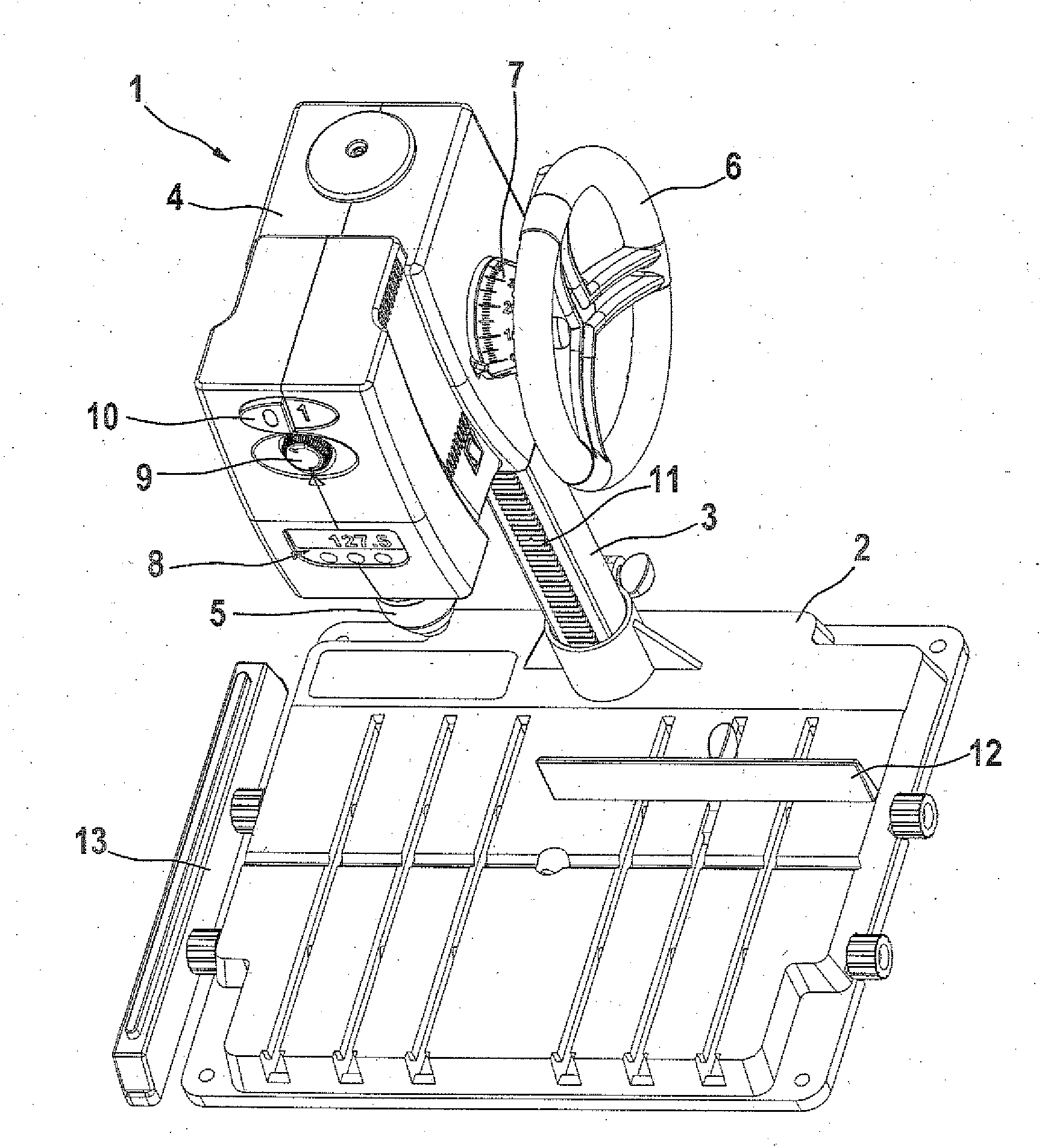
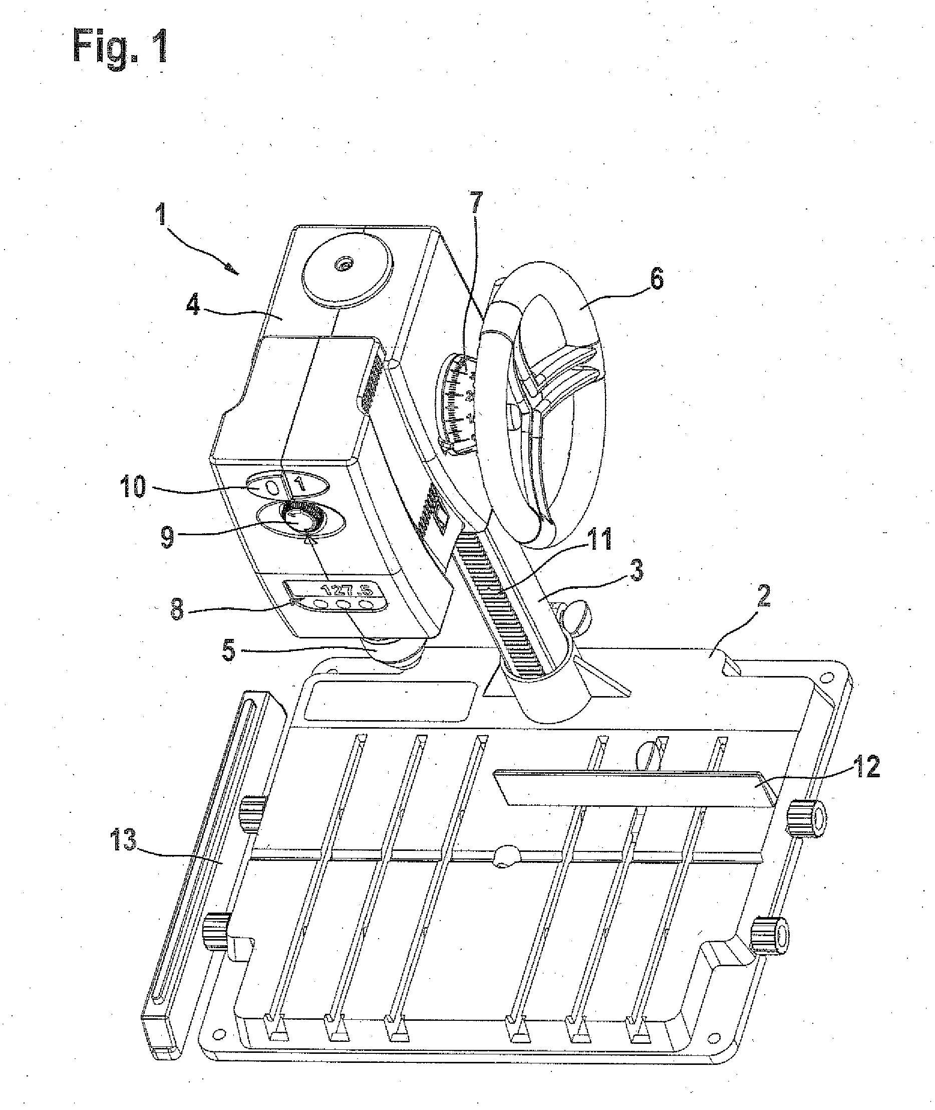
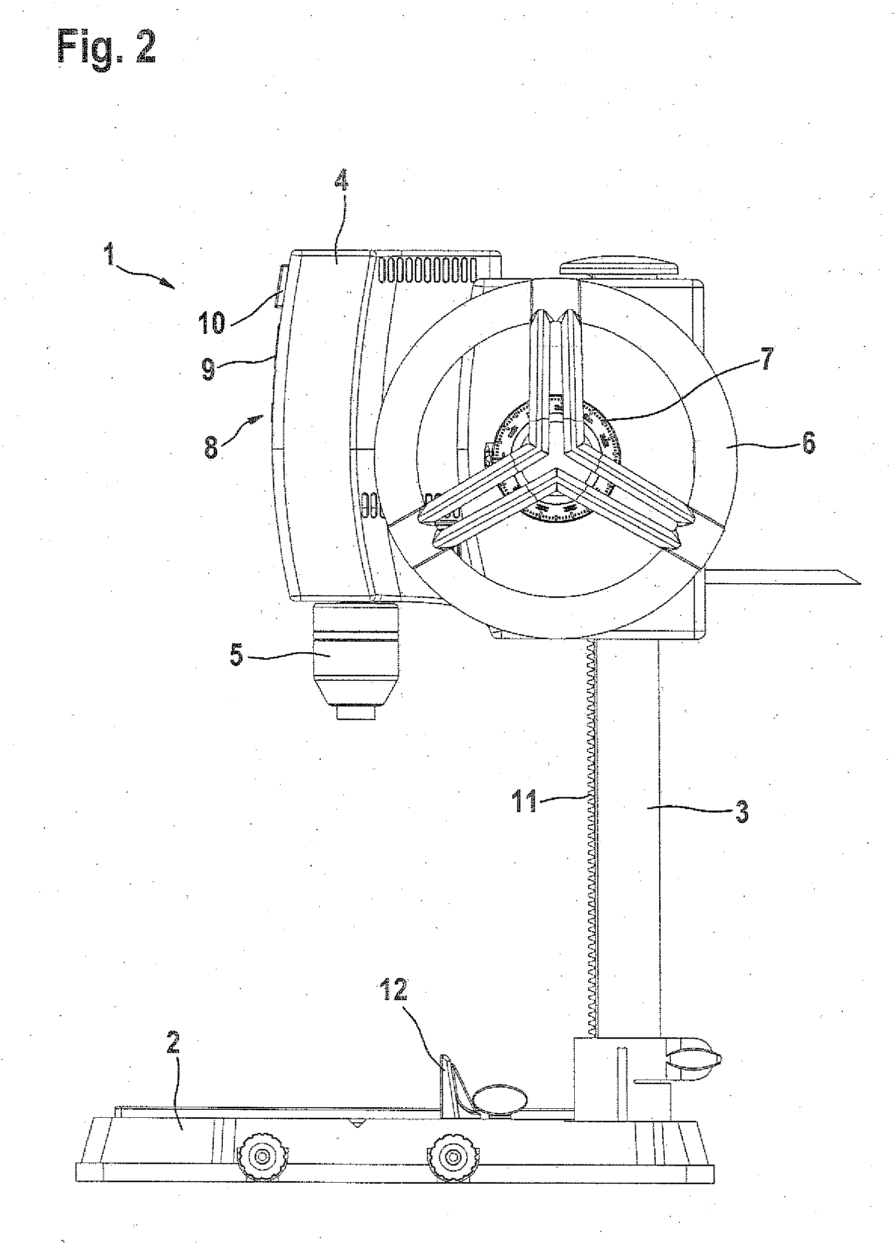
[0019]The stationary power drill 1 shown in FIGS. 1 through 3 includes a base 2, embodied as a base plate, on which a vertical guide column 3 is disposed that is the carrier of a tool housing 4 with a drill unit 5 received in the housing. The tool housing 4 is embodied as manually adjustable vertically and has a handwheel 6 that is to be actuated by the drill operator and upon the rotation of which the tool housing 4 is adjustable vertically along the guide column 3. On the handwheel 6, there is a ring scale 7 for reading out the currently set height of the tool housing.

[0020]In the front region of the tool housing 4, there is a display panel 8, embodied for instance as an LCD and on which various parameters can be displayed, such as the rpm of the drill unit 5 and the absolute position in terms of height of the tool housing. The rpm of the drill unit is meant to be set via an rpm adjuster 9 also disposed in the front region of the tool housing 4. An on / off actuation switch 10 for t...


PUM


Abstract

A stationary power drill has a drill unit disposed in a tool housing is connected to a base vertically adjustably via a guide column and is vertically adjustable along the guide column by means of a drive unit. The drive unit includes a rotating drive shaft, and a compensation spring element engaging the drive shaft and braced on the other end on the tool housing.

Description

REFERENCE TO FOREIGN PATENT APPLICATION[0001]This application is based on German Patent Application No. 10 2007 001 559.5 filed 10 Jan. 2007, upon which priority is claimed.BACKGROUND OF THE INVENTION[0002]1. Field of the Invention[0003]The invention relates to an improved stationary power drill.[0004]2. Description of the Prior Art[0005]In German Utility Model DE 20 2005 005 768 U1, a stationary power drill is described which in a tool housing has a drill head, driven by an electric motor; the tool housing is held vertically adjustably on a guide column and is braced on a base. An electric motor is disposed in the base and drives a hollow shaft, rotatably supported in the column, and moves a spindle, disposed fixedly in the tool housing, up or down depending on the direction of rotation of the drive motor. The feeding motion of the drill unit received in the tool housing is realized by way of the vertical adjusting motion of the entire tool housing along the guide column. The feedi...

Claims


Application Information

Patent Timeline
IPC IPC(8): B23B39/00
CPCB23B39/00B23B47/26B23B2250/04B23B2260/136Y10T408/99Y10T408/564Y10T408/6779Y10T408/6786Y10T408/21B23Q11/0025
Inventor FUCHS, RUDOLFMUELLER-BOYSEN, ULRICHKEUSCH, SIEGFRIEDMEIER, MARKUSRAU, SABINE
Owner ROBERT BOSCH GMBH
Why Eureka
Try Eureka