Drive type of spherical roller

a spherical roller and drive technology, applied in the field of spherical rollers, can solve the problems of spherical rollers not always having a full rolling capability, spherical rollers producing obstacles in other parts of the movement, etc., and achieve the effect of more powerful driving of spherical rollers

Inactive Publication Date: 2008-07-10
NDC CORPORATION
View PDF2 Cites 11 Cited by
  • Summary
  • Abstract
  • Description
  • Claims
  • Application Information

AI Technical Summary

Benefits of technology

[0010]The drive type of spherical roller according to the present invention comprises a spherical roller in a globular form, a housing on the undersurface of which an opening in a circular form is provided in such a way that the spherical roller is projected in a horizontal down direction, a support roller having rotatable contact with an upper side portion of the spherical roller within the housing, and a drive roller which is arranged in the housing and driven by a drive motor to rotate the spherical roller in a direction at an angle of 90 degrees different from the direction in which the support roller rotates from immediately above for friction drive, thereby driving the spherical roller to move the housing. This provides the spherical roller capable of fully rotating when moving on a rough road surface with a small contact area, producing no obstacle to the movement in other portions.
[0011]Furthermore, the drive motor is integrated with the drive roller and has a shift motor to which a pinion gear is attached such that the drive roller can move around a position in contact with the spherical roller and a position spaced from the spherical roller, and a rack which is engaged with the pinion gear and moved by the rotation of the pinion gear, whereby, when driven in the direction of travel, the spherical roller is driven by the drive motor and when driven in a direction different from the direction of travel, the drive motor is integrated with the drive roller and spaced from the position in contact with the spherical roller and the spherical roller, thereby enabling a rolling in a free direction.
[0012]In addition, the spherical roller is plurally arranged in the housing, thereby making it possible to more powerfully drive the spherical roller.
[0013]Moreover, the plural spherical rollers are serially arranged along the direction in which the drive roller rotates, thereby making it possible to concentrate their driving force in the same direction.
[0014]Subsequently, the plural spherical rollers are characterized by rotating in complete synchronization with each other, whereby the same force is simultaneously transmitted to the plural spherical rollers.

Problems solved by technology

However, the spherical roller did not always have a full rolling capability when moving on a rough road surface with a small contact area.
More specifically, the spherical roller produced an obstacle to the movement in other portions because it did not rotate during the movement.

Method used


Image

  • Drive type of spherical roller
  • Drive type of spherical roller
  • Drive type of spherical roller

Examples


Embodiment Construction

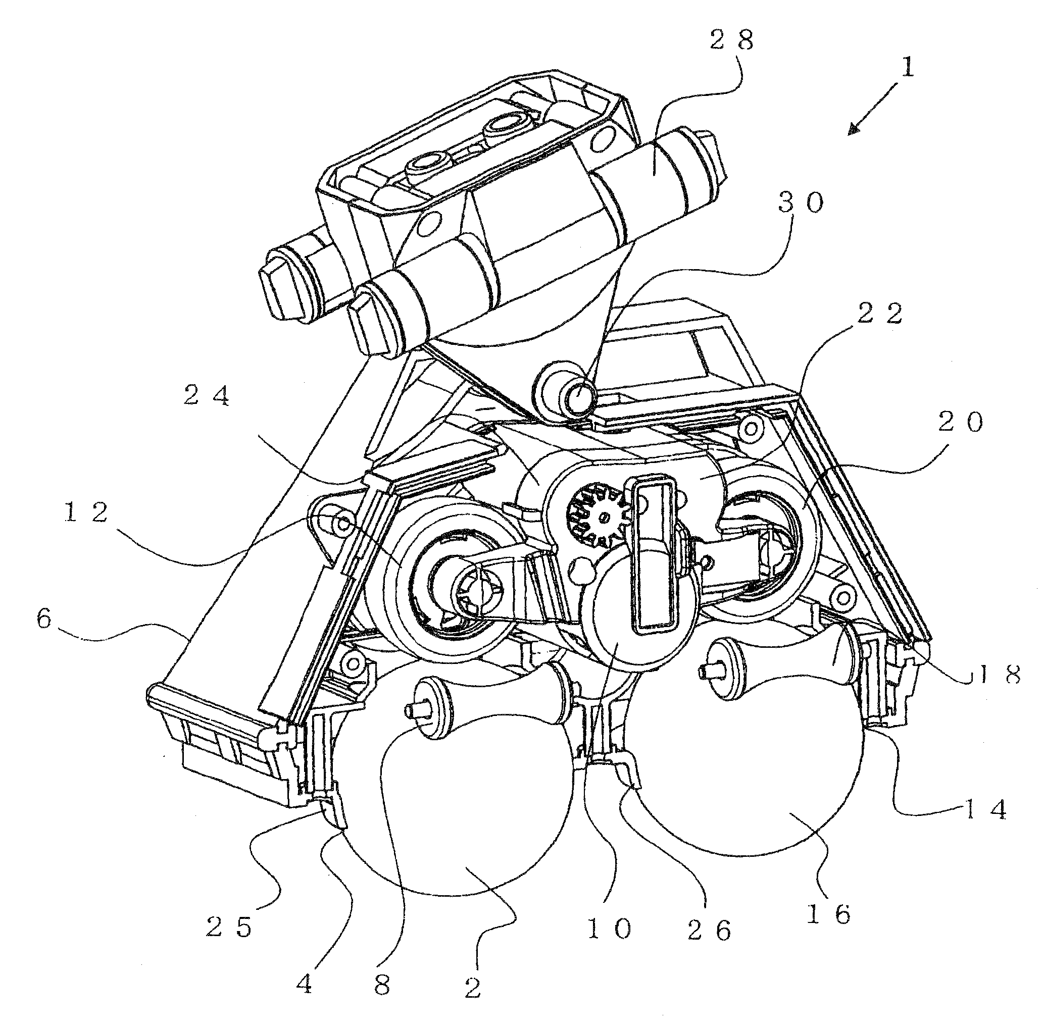
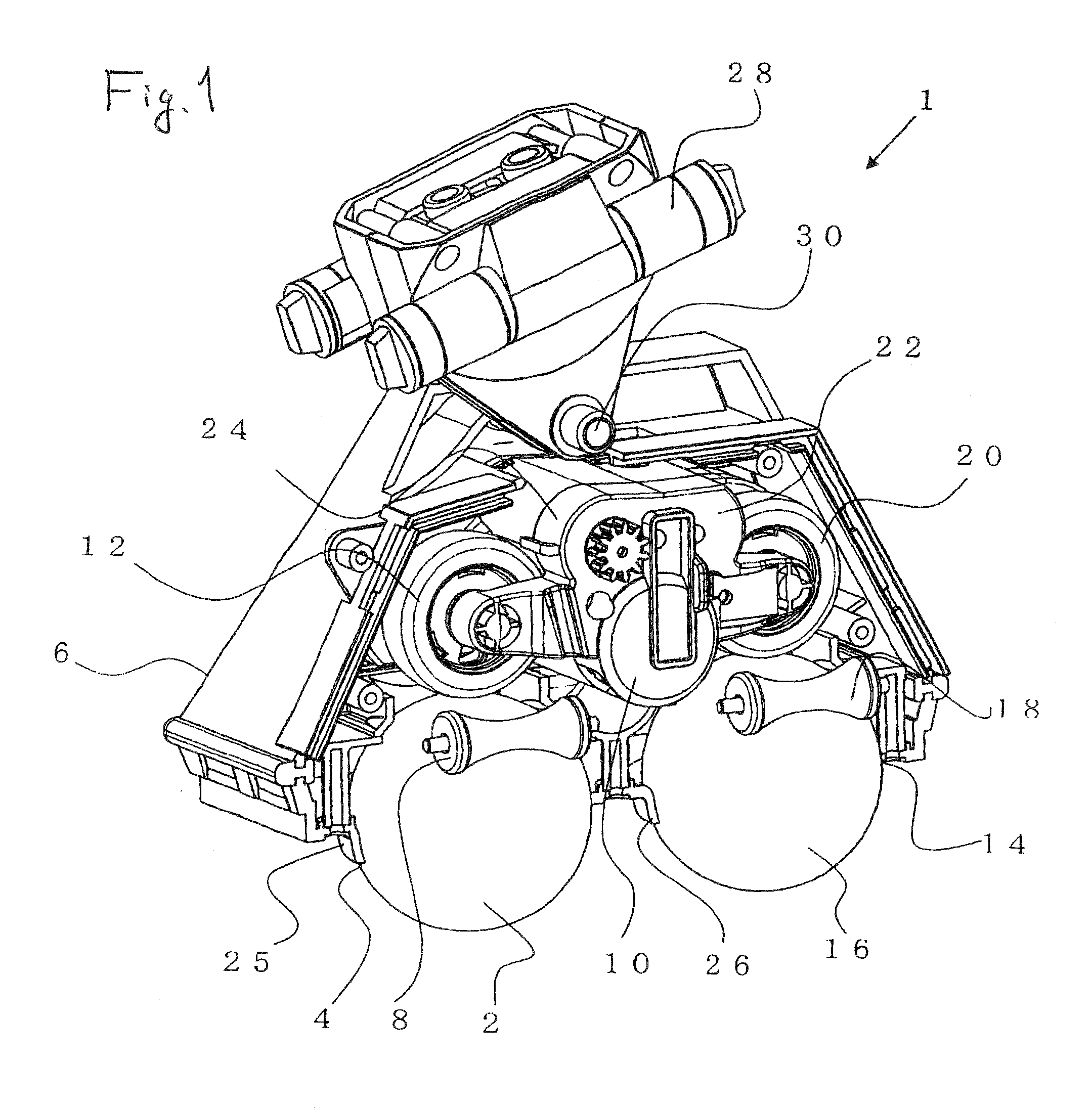
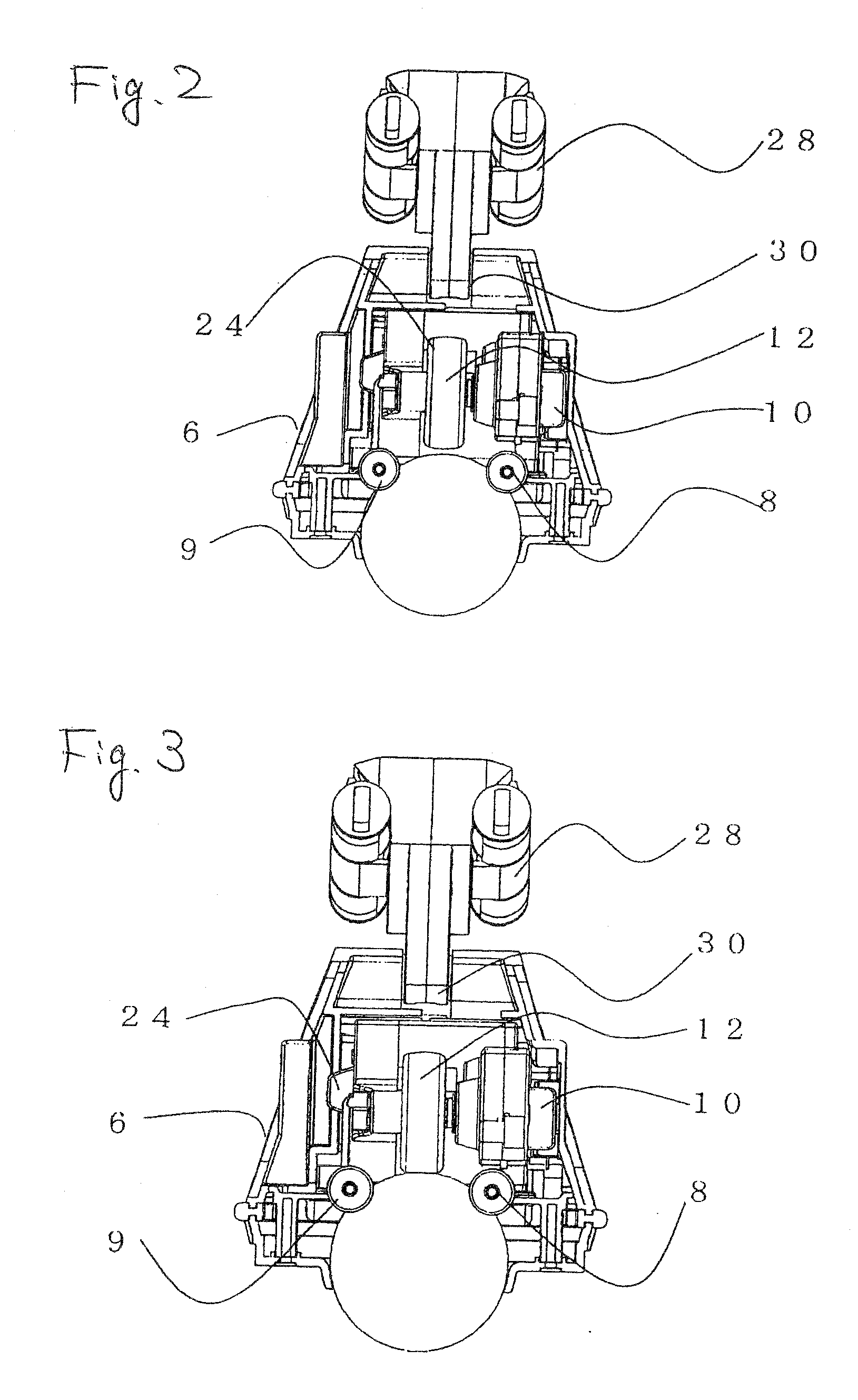
[0019]A drive type of spherical roller as the embodiment of the present invention will now be described with reference to the drawings. FIG. 1 is an overall inclined view of the drive type of spherical roller of the embodiment. FIG. 2 and FIG. 3 are side views of the drive type of spherical roller of the embodiment. FIG. 2 shows a case in which a drive roller and a spherical roller are spaced and FIG. 3 shows a case in which the drive roller and the spherical roller are in contact with each other.

[0020]FIG. 4 is an overall view of a robot to which the drive type of spherical roller according to the present invention is applied.

[0021]First of all, the embodiment will be described with reference to FIG. 1. A drive type of spherical roller 1 as the embodiment of the present invention comprises a spherical roller 2 in a globular form, a housing 6 on the undersurface of which an opening 4 in a circular form is provided in such a way that the spherical roller 2 is projected in a horizonta...


PUM


Abstract

To provide a spherical roller which is capable of fully rotating when moving on a rough road surface with a small contact area and which produces no obstacle to the movement in other portions.
The present invention comprises a spherical roller in a globular form, a housing on the undersurface of which an opening in a circular form is provided in such a way that the spherical roller is projected in a horizontal down direction, a support roller having rotatable contact with an upper side portion of the spherical roller within the housing, and a drive roller which is arranged in the housing and driven by a drive motor to rotate the spherical roller in a direction at an angle of 90 degrees different from the direction in which the support roller rotates from immediately above for friction drive, thereby driving the spherical roller to move the housing.

Description

TECHNICAL FIELD[0001]The present invention relates to a spherical roller, and particularly to a spherical roller which can be driven.BACKGROUND ART[0002]A spherical roller is being used as a structural member of a bearing or a pen point of a ballpoint pen. In addition, the spherical roller may be used as a device for detecting the amount of rotation like Japanese Unexamined Patent Publication No. 3(1991-27732).DISCLOSURE OF THE INVENTION [0003]Incidentally, a spherical roller can be used as a tire or a roller by being attached to the bottom surface of a shaft portion such as a foot portion of a robot. Particularly, the spherical roller can be rotated in various directions without changing the direction of the roller and thus is excellent in having a degree of freedom in comparison with the tire rotating in one direction.[0004]However, the spherical roller did not always have a full rolling capability when moving on a rough road surface with a small contact area. More specifically, t...

Claims


Application Information

Patent Timeline
Patent Type & Authority Applications(United States)
IPC IPC(8): F16H37/00F16H15/38
CPCB60B19/14B60K7/00B62D57/00B60K2007/0046B60K17/043
Inventor KOIKE, TOMOHIKO
Owner NDC CORPORATION
Why Eureka
Try Eureka