In-Wall Waste Receptacles For Hospital and Laboratory Environments

Inactive Publication Date: 2008-07-17
OPTIMUS SERVICES
View PDF11 Cites 9 Cited by
  • Summary
  • Abstract
  • Description
  • Claims
  • Application Information

AI Technical Summary

Benefits of technology

[0022]The tube is then inserted into the wall opening. After the bag is full, the bag may be removed and a new bag inserted. The bag maintains the sterility of the cartridge and hence helps maintain the sterility of the environment. If a bag breaks, the tube may be closed with a plug and disposed of. Since the tube is made of lightweight plastic, disposal is easy and cost-conscious. The receptacles may also be fitted with special sharps plugs to allow disposal of sharp instruments such as needles or scapula tips. The special sharp plugs are adapted to prevent a person from being pri

Problems solved by technology

When waste is generated in the medical or scientific environment, it consumes valuable space.
Fu

Method used


Image

  • In-Wall Waste Receptacles For Hospital and Laboratory Environments
  • In-Wall Waste Receptacles For Hospital and Laboratory Environments
  • In-Wall Waste Receptacles For Hospital and Laboratory Environments

Examples


Embodiment Construction

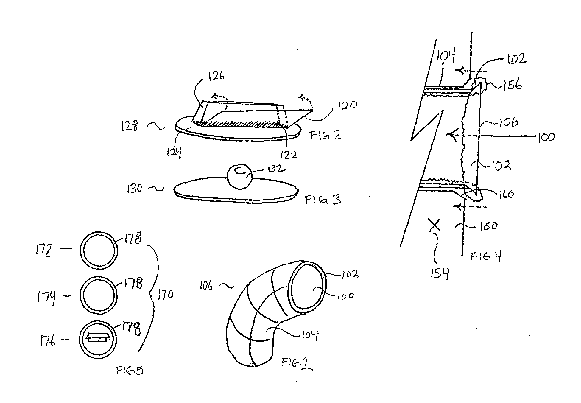
[0031]As seen in FIG. 1, the waste receptacle cartridge 106 has a preferred shape similar to a rounded upside-down “L”. Other shapes may used, provided they help hold the cartridge into wall. For example, a non-upside-down “L” shape would not be appropriate.

[0032]The outside molded surface can be a variety of textures but is preferably composed, as is the entirety of the cartridge 106, out of lightweight plastic. The shaping and texture may be adapted, as it is in the preferred embodiment, to allow a smooth sliding action into or out of the second wall-element. Alternatively, the texture may be adjusted to make movement more resistant.

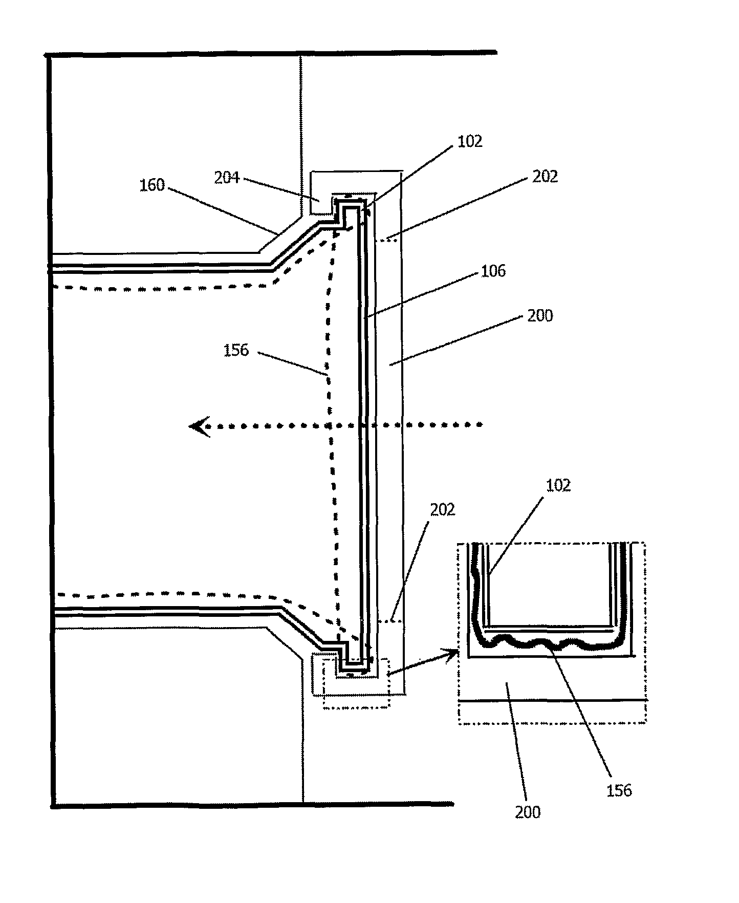
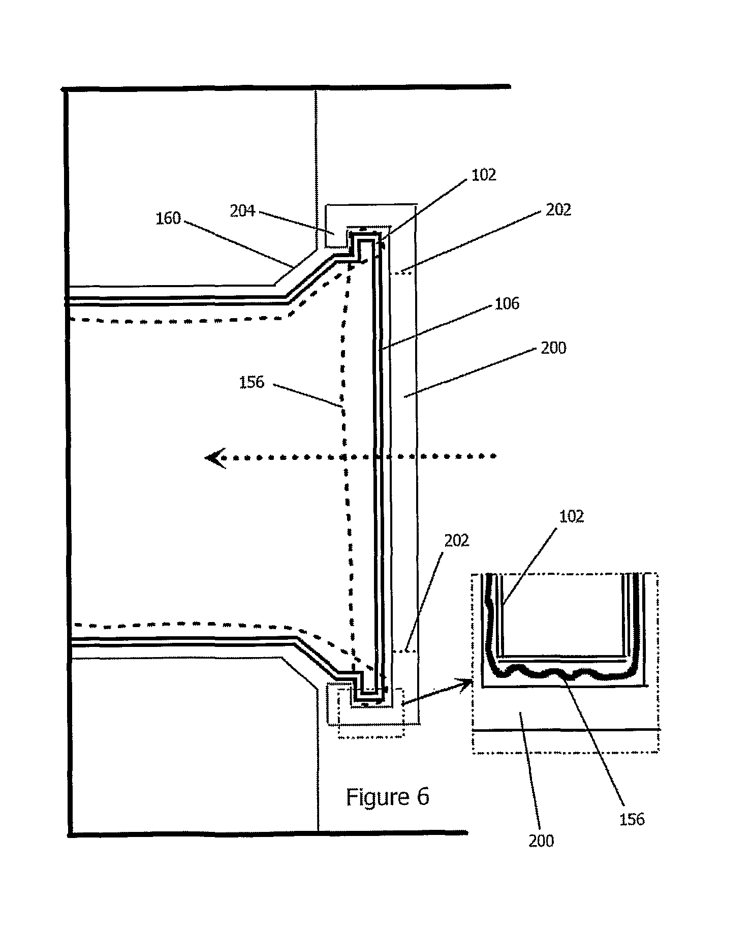
[0033]The tube structure of 106 defines an interior 100. As can be seen, tube 106 has a bottom surface providing a tube with a single entrance. The outside perimeter of lip 102 is designed to fit snugly within the second wall-element and to allow a variety of plugs to fit inside the perimeter of the lip.

[0034]In FIG. 2, a sharps plug 128 is shown. The ...


PUM


Abstract

A trash receptacle comprising an entrance in a wall adapted to receive a disposable, lightweight, and preferably plastic cartridge is disclosed. The cartridge is adapted to dispose its center of gravity in a manner that maintains the cartridge within the wall entrance under its own empty weight. The cartridge may further receive a disposable bag to maintain sterility. The bag can be held in place by a sealing device, such as an O-ring, which, in one embodiment, snaps over said bag onto said cartridge, said O-ring or other sealing device preferably color-coded to indicate the type of waste to be disposed in said cartridge. The cartridge is also adapted to receive a plug to allow disposal of sharps. If a bag breaks, the cartridge may be sealed and disposed of, thereby maintaining a sanitary and sterile environment. The receptacles may be arrayed in a wall, thereby providing a convenient waste disposal system that does not interfere with critical working space.

Description

CROSS-REFERENCE TO RELATED APPLICATIONS[0001]This application claims the benefit of provisional patent application U.S. Ser. No. 60 / 701,106, filed Jul. 20, 2005 by the present inventor. The contents of U.S. Ser. No. 60 / 701,106 are expressly incorporated herein by reference thereto.[0002]The following references are hereby explicitly incorporated by reference thereto:[0003]U.S. Pat. No. 4,925,048[0004]Applications filed along with present application by current inventor on this date entitled:[0005]IN-CEILING FOCUS LOCATED SURGICAL LIGHTING[0006]HOSPITAL OPERATING ROOM RE-DESIGN[0007]AMBIENT LIGHTING IN HOSPITAL SURGICAL ENVIRONMENTS[0008]USE OF ULTRAVIOLET GERMICIDAL IRRADIATION IN HEALTH CARE ENVIRONMENTS[0009]MULTIFUNCTIONAL FLOOR PODS[0010]RE-DESIGN OF OPERATING ROOM TABLES[0011]ROBOTIC FLOOR CLEANING WITH STERILE, DISPOSABLE CARTRIDGESBACKGROUND OF THE INVENTION[0012]1. Field of Invention[0013]The present invention relates to a device and method for disposing of waste in medical ...

Claims


Application Information

Patent Timeline
IPC IPC(8): B65F1/06B65F1/14
CPCA47L11/302A47L11/40A47L2201/00A61B19/0287A61B19/0288A61B2019/0202H01R27/02A61B2019/0267B01L1/50B65F1/0093B65F1/06E04B5/48H01R13/005A61B2019/025A61B2050/314A61B2050/005A61B50/13A61B50/36A61B50/362
Inventor MANGIARDI, JOHN R.
Owner OPTIMUS SERVICES
Why Eureka
Try Eureka