Method and apparatus for high-gain magnetic resonance imaging

a magnetic resonance imaging and high-gain technology, applied in the field of diagnostic medical imaging, can solve the problems of high cost of both purchase and maintenance of mri systems, high cost of design and manufacture of such systems, and increase the use of this versatile imaging technology. to achieve the effect of improving the signal-to-noise ratio

Inactive Publication Date: 2008-07-17
TURSIOP TECH
View PDF8 Cites 42 Cited by
  • Summary
  • Abstract
  • Description
  • Claims
  • Application Information

AI Technical Summary

Benefits of technology

[0007]The present invention includes a method and apparatus for Magnetic Resonance Imaging that uses imaging receiver coils with high Signal-to-Noise-Ratios (SNR) to provide increased performance at known high static magnetic field strengths and / or to allow the use of lower static magnetic field strengths at lower costs without loss of performance compared to conventional systems operating at high static magnetic field strengths. Various coil arrangements and system configurations are disclosed that exploit the electrical properties of low-resistance imaging coils made at least partly from carbon nanotube materials, which are so-called “ballistic conductors” with resistance that does not increase significantly with length of conductor. An imaging system of the invention can include a homogeneous static magnetic field, or a specially-tailored inhomogeneous static magnetic field.

Problems solved by technology

A significant factor impeding further increased use of this versatile imaging technology is the typically high cost of both purchase and maintenance of MRI systems.
The costs associated with the design and manufacture of such systems are due mainly to the need to generate large and very homogeneous static magnetic fields.
Additional cost is associated with the need to electronically generate gradient fields for imaging with such systems.
However, the conventional approach of increasing performance by using even higher static magnetic fields is prohibitively expensive, and does not work in many cases due to imaging artifacts that appear at these ultra-high fields.

Method used


Image

  • Method and apparatus for high-gain magnetic resonance imaging
  • Method and apparatus for high-gain magnetic resonance imaging
  • Method and apparatus for high-gain magnetic resonance imaging

Examples


Embodiment Construction

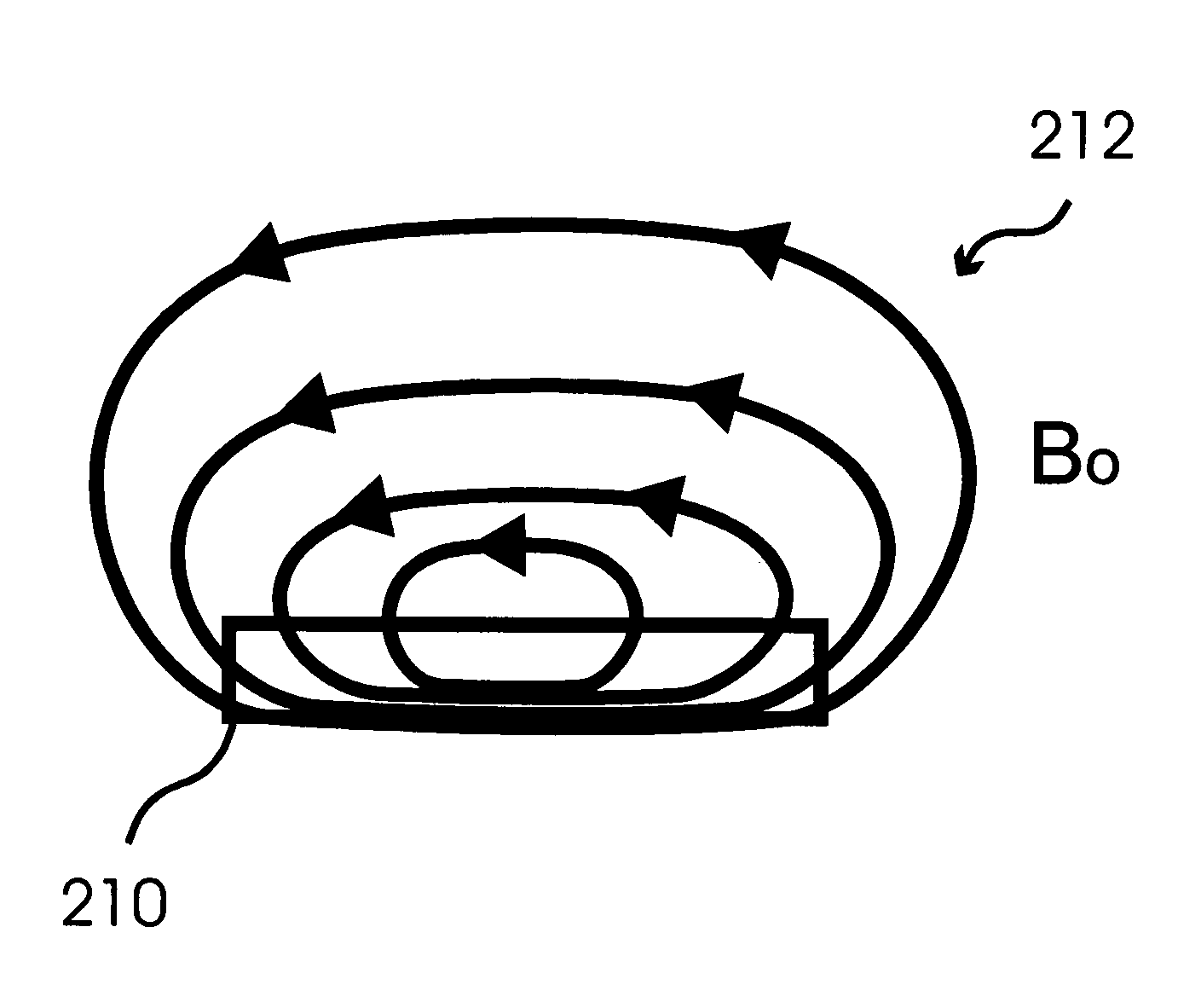
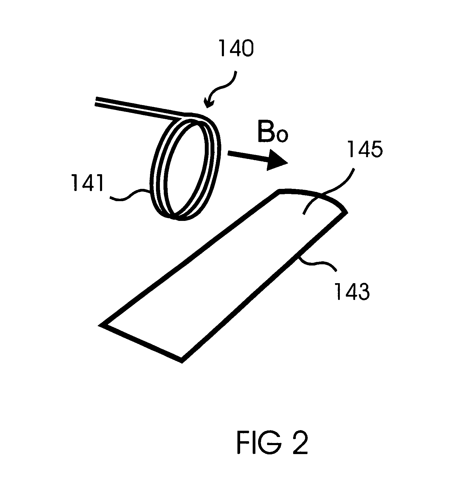
[0051]The imaging system of the present invention includes a magnet system having at least one magnet for producing either a homogeneous or an inhomogeneous static magnetic field within the desired volume to be imaged, together with at least one Radio Frequency (RF) transmission coil, and at least one RF receiving coil made at least partially of carbon nanotube material. In some embodiments, the same coil is used as both the transmission coil and the receiving coil.

[0052]Carbon nanotubes have many interesting electrical, mechanical and thermal properties. Specifically, they possess the property of ballistic electron transport, wherein the electrons transported by the conductor do not get significantly scattered during transport, such that the electrical resistance offered by the conductor to a current does not increase with length. In contrast, the resistance of a standard (metallic) electrical conductor increases linearly with length, other things being equal. Furthermore, ballisti...


PUM


Abstract

An apparatus is disclosed for Magnetic Resonance Imaging with specialized imaging coils possessing high Signal-to-Noise-Ratios (SNR). Radio Frequency transmitting and / or Radio Frequency receiving elements include carbon nanotube material, a ballistic electrical conductor having a resistance that does not increase significantly with length. The shapes of the receiving and transmitting elements can be linear, curvilinear, or coiled. The carbon nanotube material can be layered. Due to their enhanced SNR properties, preferred embodiments have smaller static magnetic field strengths with imaging quality comparable to known field systems, leading to substantial reductions in system size and cost. Other preferred embodiments provide enhanced imaging with known MRI static magnetic field strengths.

Description

CROSS-REFERENCES TO RELATED APPLICATIONS[0001]This application is a continuation in part entitled to the benefit of U.S. patent application Ser. No. 11 / 582,094, entitled “METHOD AND APPARATUS FOR HIGH GAIN MAGNETIC RESONANCE IMAGING”, filed Oct. 17, 2006, herein incorporated by reference.[0002]U.S. patent application Ser. No. 11 / 582,094 is entitled to the benefit of U.S. Provisional Patent Application No. 60 / 727,924, entitled “METHOD AND APPARATUS FOR HIGH GAIN MAGNETIC RESONANCE IMAGING”, filed Oct. 18, 2005, herein incorporated by reference.FIELD OF THE INVENTION[0003]This invention relates to diagnostic medical imaging, and more particularly to Magnetic Resonance Imaging at high Signal-to-Noise-Ratios.BACKGROUND OF THE INVENTION[0004]Magnetic Resonance Imaging (MRI) technology is common today in larger medical institutions worldwide, and has led to huge benefits in the practice of medicine. A significant factor impeding further increased use of this versatile imaging technology i...

Claims


Application Information

Patent Timeline
Patent Type & Authority Applications(United States)
IPC IPC(8): G01R33/32
CPCB82Y10/00B82Y25/00B82Y30/00G01R33/341G01R33/34046G01R33/34076G01R33/34007
Inventor VISWANATHAN, RAJU R.
Owner TURSIOP TECH
Why Eureka
Try Eureka