
Handheld System for Radar Detection

Inactive Publication Date: 2008-07-17
ROSENBURY ERWIN T
View PDF14 Cites 31 Cited by
  • Summary
  • Abstract
  • Description
  • Claims
  • Application Information

AI Technical Summary

Benefits of technology

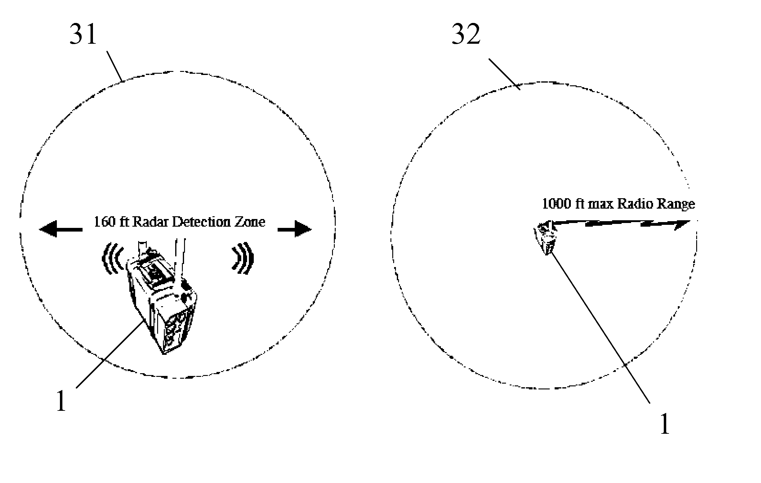
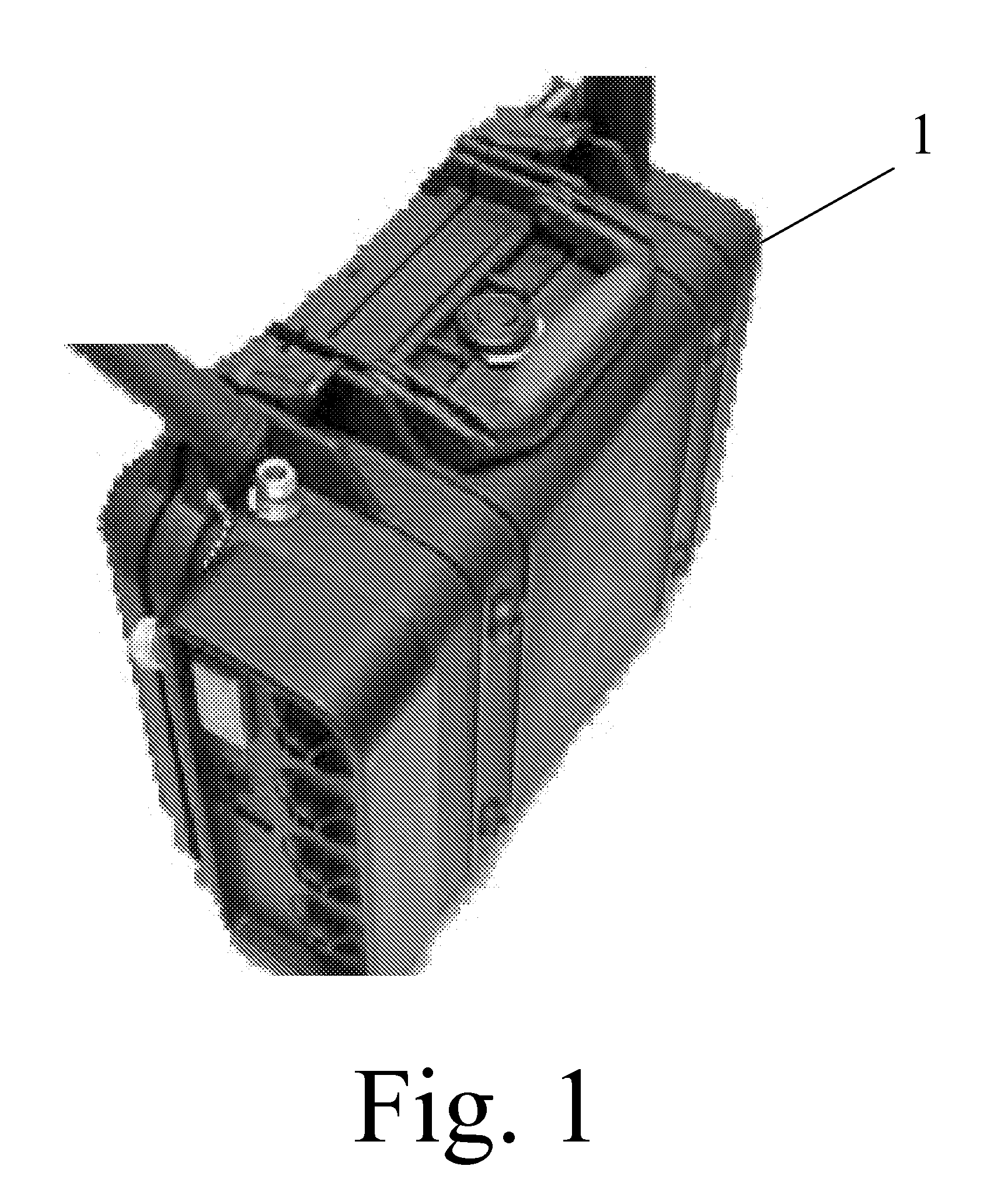
[0010]The present invention is designed as a personal handheld radar detection device and consists of a MicroPower Radar (MPR), a data acquisition (DAQ) element and a processor. Radar sends a short, low-amplitude signal of radio-frequency (RF) energy toward the target. This signal reflects from the target and is received as a Doppler change in signal amplitude. The radar's RF energy is in the radio frequency band and operates at much lower powers than many mobile devices such as cell phones. RF has the advantages of penetrating foliage while operating at one-tenth the power of a cellular or cordless phone. This Doppler System change in signal amplitude is filtered, amplified and presented to the DAQ. The DAQ converts the analog Doppler signal into a digital bit-stream and passed to the radar processor.
[0012]The present invention teaches a radar detection system that provides high reliability, low false alarm personnel detection through out a 160′ precision detection zone. The system is small in size, operates all night on standard alkaline batteries (D-cells), provides an alarm indicator to a wireless key-fob in addition to other audible and visual indicators.

Problems solved by technology

One shortcoming of such devices is that either in military or civilian use they are not constructed in such a manner that permits them to be handheld, portable, and rugged enough to withstand various environmental conditions such as wind, rain, and sand.
Another shortcoming inherent with prior art devices are that, when designed to be portable, they are not equipped with remote means for one or more uses to which a detection signal or other information can be transmitted.
Another well-known problem in the prior art is that similar portable devices known in the prior art are battery powered which often means that they have a limited operating time period and need recharged on a daily basis.

Method used


Image

  • Handheld System for Radar Detection
  • Handheld System for Radar Detection
  • Handheld System for Radar Detection

Examples


Embodiment Construction

[0022]In the following detailed description of the invention of exemplary embodiments of the invention, reference is made to the accompanying drawings (where like numbers represent like elements), which form a part hereof, and in which is shown by way of illustration specific exemplary embodiments in which the invention may be practiced. These embodiments are described in sufficient detail to enable those skilled in the art to practice the invention, but other embodiments may be utilized and logical, functional, mechanical, electrical, and other changes may be made without departing from the scope of the present invention. The following detailed description is therefore, not to be taken in a limiting sense, and the scope of the present invention is defined only by the appended claims.

[0023]In the following description, numerous specific details are set forth to provide a thorough understanding of the invention. However, it is understood that the invention may be practiced without th...


PUM


Abstract

The present invention is a radar platform that detects intruders and wirelessly reports to a key-fob. The entire radar platform is water-resistant and two banks of batteries are included for convenience or extended operation time. The device consists of a MicroPower Radar (MPR), a data acquisition (DAQ) element and a processor. Radar sends a short, low-amplitude signal of radio-frequency (RF) energy toward the target. This signal reflects from the target and is received as a Doppler change in signal amplitude. The radar's RF energy is in the radio frequency band and operates at much lower powers than many mobile devices such as cell phones. This Doppler System change in signal amplitude is filtered, amplified and presented to the DAQ. The DAQ converts the analog Doppler signal into a digital bit-stream and passed to the radar processor. Proprietary software analysis is performed to further filter and to make an alarm determination.

Description

FEDERALLY SPONSORED RESEARCH[0001]Not ApplicableSEQUENCE LISTING OR PROGRAM[0002]Not ApplicableCROSS REFERENCE TO RELATED APPLICATIONS[0003]Not ApplicableTECHNICAL FIELD OF THE INVENTION[0004]The present invention relates generally to radar systems. More specifically, the present invention relates to a wireless portable handheld radar detection system.BACKGROUND OF THE INVENTION[0005]Various devices known in the prior art have been devised that utilize radar to detect objects. One shortcoming of such devices is that either in military or civilian use they are not constructed in such a manner that permits them to be handheld, portable, and rugged enough to withstand various environmental conditions such as wind, rain, and sand.[0006]Another shortcoming inherent with prior art devices are that, when designed to be portable, they are not equipped with remote means for one or more uses to which a detection signal or other information can be transmitted. It is therefore a desirable featu...

Claims


Application Information

Patent Timeline
IPC IPC(8): G01S13/62
CPCG01S7/003G01S13/56G01S13/52G01S7/03
Inventor ROSENBURY, ERWIN T.
Owner ROSENBURY ERWIN T
Learn More