
Novel circuit interrupting device with automatic end-of-life test

a technology of circuit interrupting device and automatic end-of-life test, which is applied in the direction of earth fault current operation switch, protective switch details, emergency protective arrangements for limiting excess voltage/current, etc., and can solve the problem that the circuit interrupting device cannot be res

Inactive Publication Date: 2008-07-17
HUANG HUADAO
View PDF27 Cites 22 Cited by
  • Summary
  • Abstract
  • Description
  • Claims
  • Application Information

AI Technical Summary

Benefits of technology

[0027]When the depression of the test button does not cause a simulation of a fault to trip the circuit interrupting device, a further depression of the test button at the second level causes the circuit interrupting device to be mechanically tripped.
[0029]Finally, the present invention provides a method for testing the components of a ground fault circuit interrupter (GFCI). The method includes properly connecting the input power line and the output power line of the GFCI when the reset button of the GFCI is at a tripped position; and monitoring a showing up of a reset indicator light. When the reset indicator light is lit, the components of the GFCI are functioned properly. When the reset button of said GFCI is not at a tripped position, one should depress a test button at a first level to allow a test of the components of the GFCI and monitor the reset indicator light to be lit.

Problems solved by technology

When at least one of the components of the circuit interrupting device is not functioned properly, the circuit interrupting device cannot be reset.

Method used


Image

  • Novel circuit interrupting device with automatic end-of-life test
  • Novel circuit interrupting device with automatic end-of-life test
  • Novel circuit interrupting device with automatic end-of-life test

Examples


Embodiment Construction

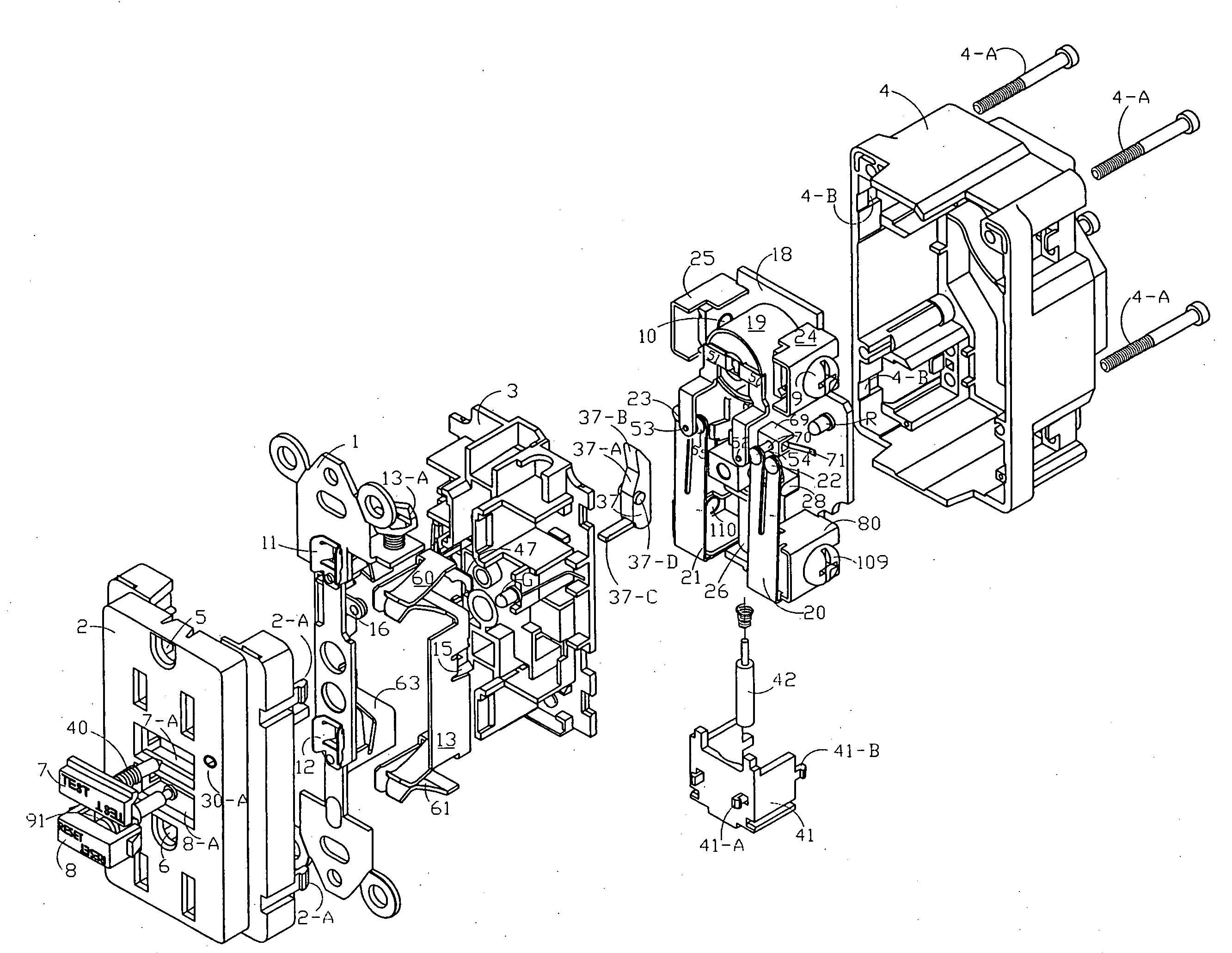
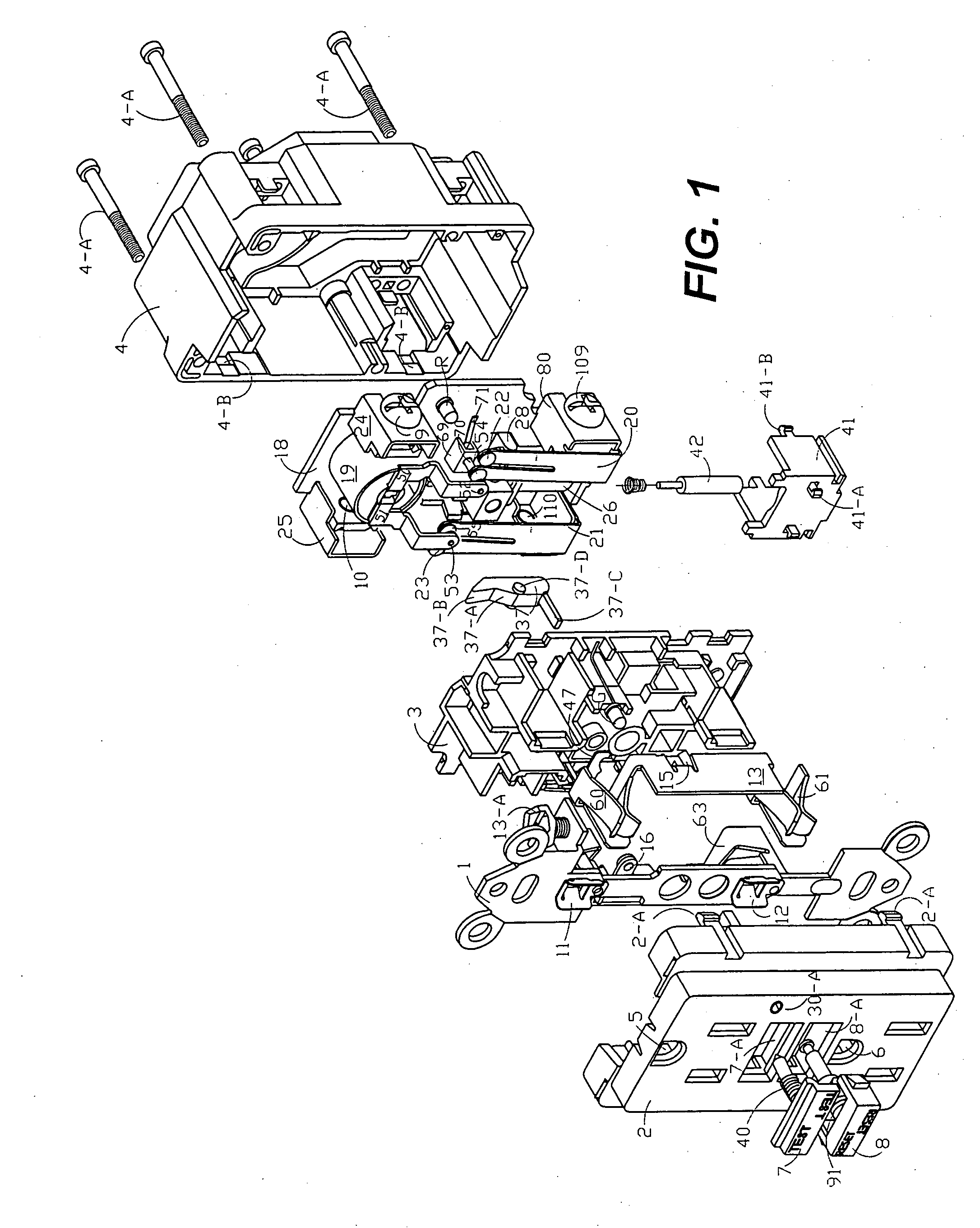
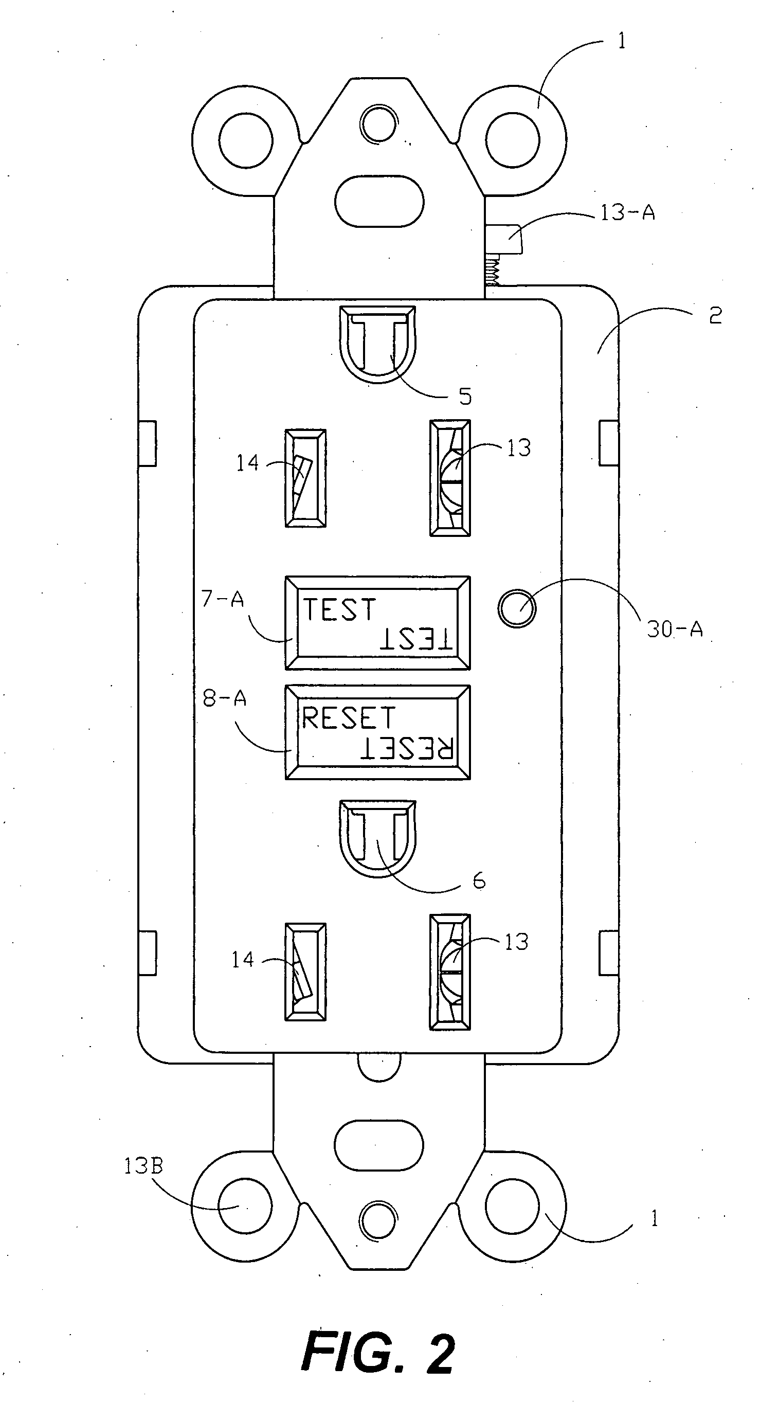
[0047]The present invention describes a circuit interrupting device, which includes, but is not limited to, a ground fault circuit interrupter (GFCI), an arc fault circuit interrupter (AFCI), an immersion detection circuit interrupter, an appliance leakage circuit interrupter, or a circuit breaker. The preferred circuit interrupting device is a GFCI.

[0048]The following experimental designs and result are illustrative, but not limiting the scope of the present invention. Reasonable variations, such as those occur to reasonable artisan, can be made herein without departing from the scope of the present invention. For example, while an exemplary GFCI is illustrated and described with respect to the Figures, one skilled in the art will appreciate that the description equally applies to other circuit interrupting devices. Also, in describing the invention, specific terminology is employed for the sake of clarity. However, the invention is not intended to be limited to the specific termin...


PUM


Abstract

The present invention provides a novel circuit interrupting device which is capable of performing an automatic end-of-life test using a status test switch (KR-1), when the device is properly wired and the reset button is at a tripped state. The present invention is further characterized by its novel reset mechanism using a reset start switch (KR-4), which comprises a spring piece, a conductive pin, and a 7-shaped metal piece. Additionally, the present invention provides a novel electrical connection between an input power end, an output power end, and a user accessible end to establish or discontinue electricity in the circuit interrupting device. Furthermore, the present invention provides a novel test mechanism which uses a test button in connection with a rotatable lever to provide a dual test function to either test the components of the circuit interrupting device when the power is on and the reset button is at a reset state, or provide a mechanical trip when the reset button cannot be tripped by artificially generating an electric leakage current. Finally, the present invention provides a method to monitor the end-of-life of the device.

Description

RELATED APPLICATION[0001]This patent application claims the priority of Chinese Patent Application No. 200720103255.6, filed on Jan. 17, 2007, which is herein incorporated by reference.FIELD OF THE INVENTION[0002]The present invention relates to a novel circuit interrupting device which is capable of performing an automatic end-of-life test due to a status test switch (KR-1), when the device is properly wired and the reset button is at a tripped state. The present invention is further characterized by a novel reset mechanism having a reset start switch (KR-4), which comprises a spring piece, a conductive pin, and a 7-shaped metal piece. Additionally, the present invention contains a novel electrical connection between an input power end, an output power end, and a user accessible end to establish or discontinue electricity. Furthermore, the present invention relates to a novel test mechanism which uses a test button in connection with a rotatable lever to provide a dual functioned t...

Claims


Application Information

Patent Timeline
Patent Type & Authority Applications(United States)
IPC IPC(8): H02H3/00
CPCH01H2071/044H01H83/04
Inventor HUANG, HUADAOLU, HUAYANG
Owner HUANG HUADAO
Learn More