Combination assembly of led and heat sink

a technology of led and heat sink, which is applied in the direction of lighting and heating apparatus, semiconductor devices for light sources, and modification by conduction heat transfer, etc. it can solve the problems of poor heat transmission rate, no fine solution to fix, and high heat produced by luminance led, and achieve greater heat transmission efficiency and heat transmission performan

Inactive Publication Date: 2008-07-17
TAI SOL ELECTRONICS
View PDF10 Cites 45 Cited by
  • Summary
  • Abstract
  • Description
  • Claims
  • Application Information

AI Technical Summary

Benefits of technology

[0008]According to the objective of the present invention, a combination assembly of LED and heat sink includes a heat sink having a substrate and a plurality of fins, a circuit board provided on the substrate and at least one LED unit provided on the heat sink and electrically connected to the circuit board. The heat of the LED unit may be transmitted to the heat sink directly for heat transmission. The present invention has a greater heat transmission efficiency.

Problems solved by technology

In present days, the high luminance LED produces high heat, and there is no fine solution to fix it yet.
However, this technique provides three intermediates between the LED chip and the heat sink, which is the one performing heat transmission, that make the heat transmission rate is poor because the intermediates cause a greater heat resistance.
These intermediates also cause the problem of high heat resistance and low heat transmission rate.

Method used


Image

  • Combination assembly of led and heat sink
  • Combination assembly of led and heat sink
  • Combination assembly of led and heat sink

Examples


first embodiment

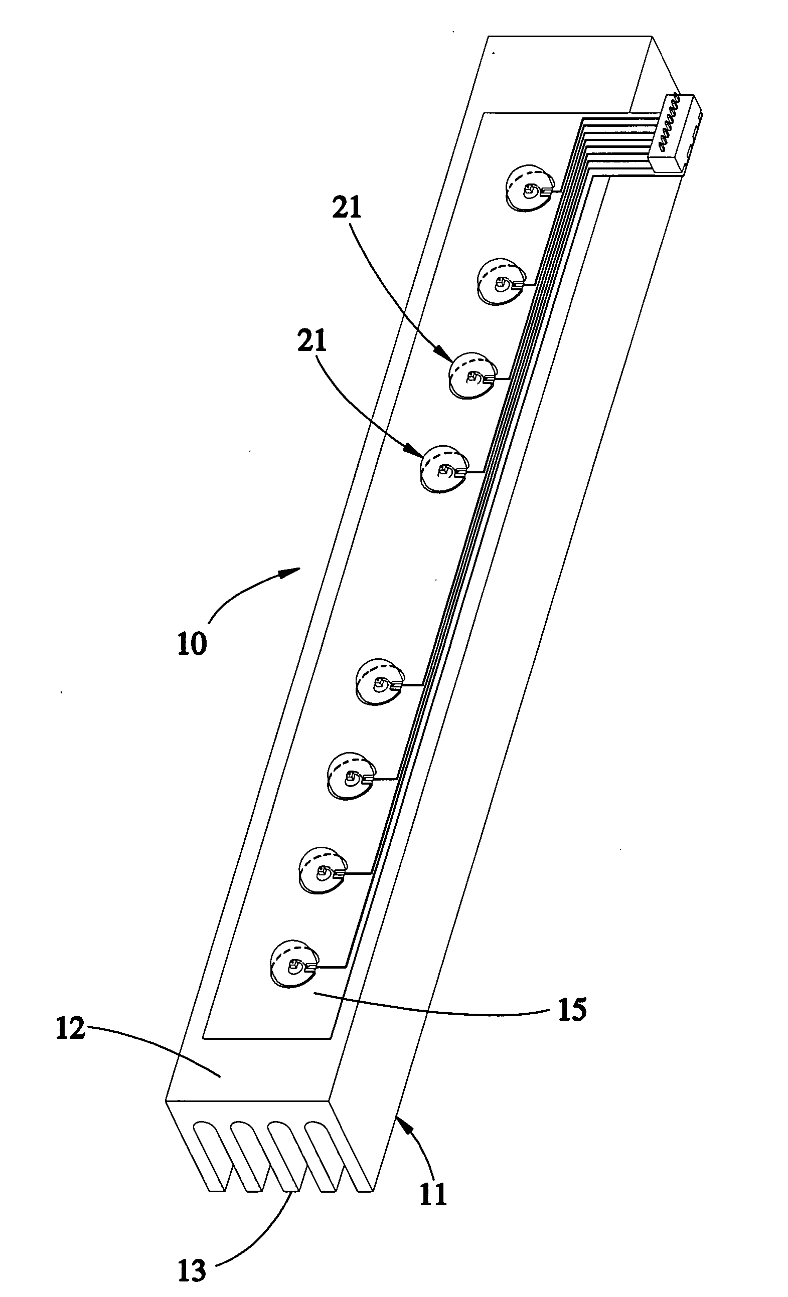
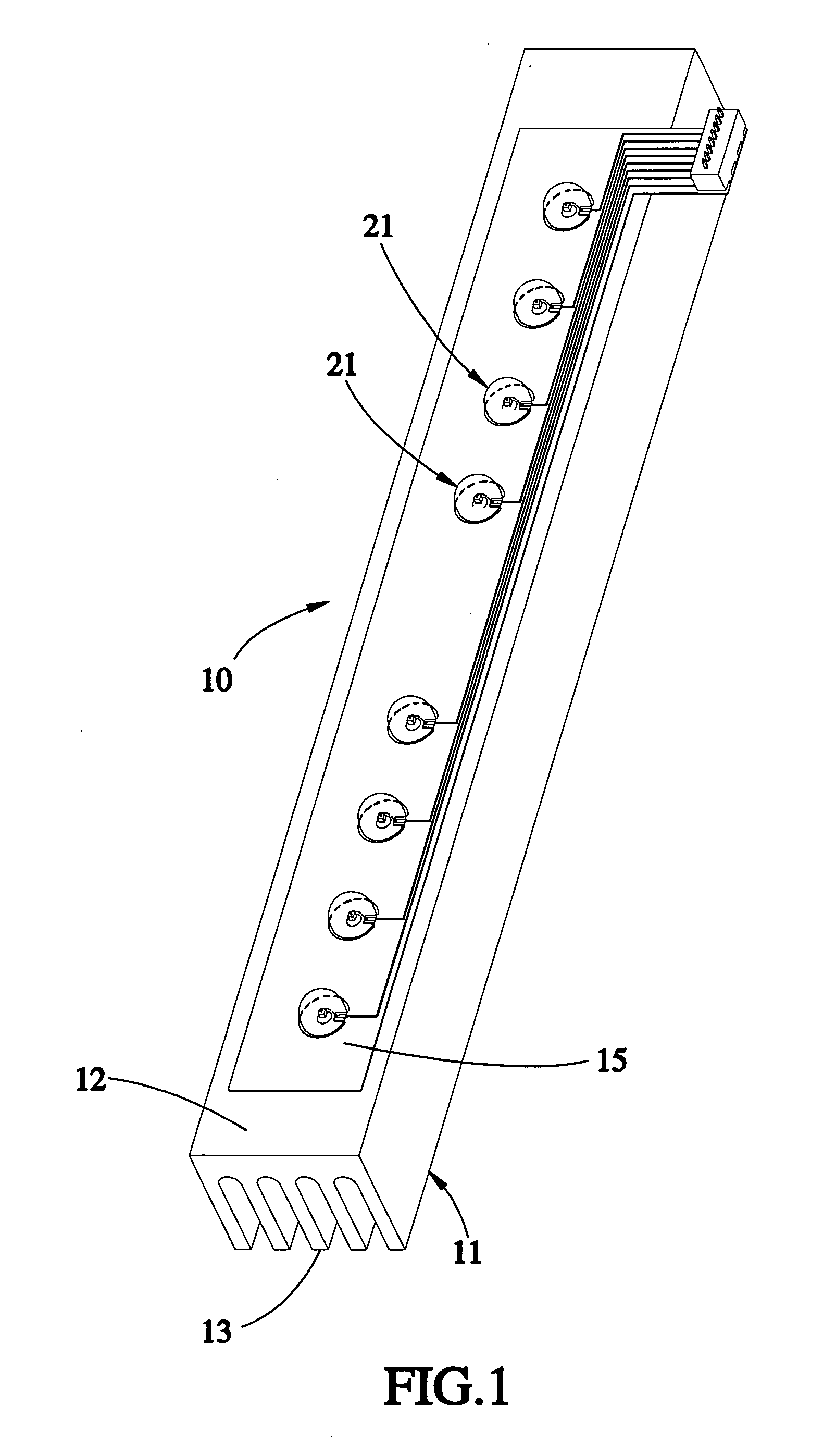
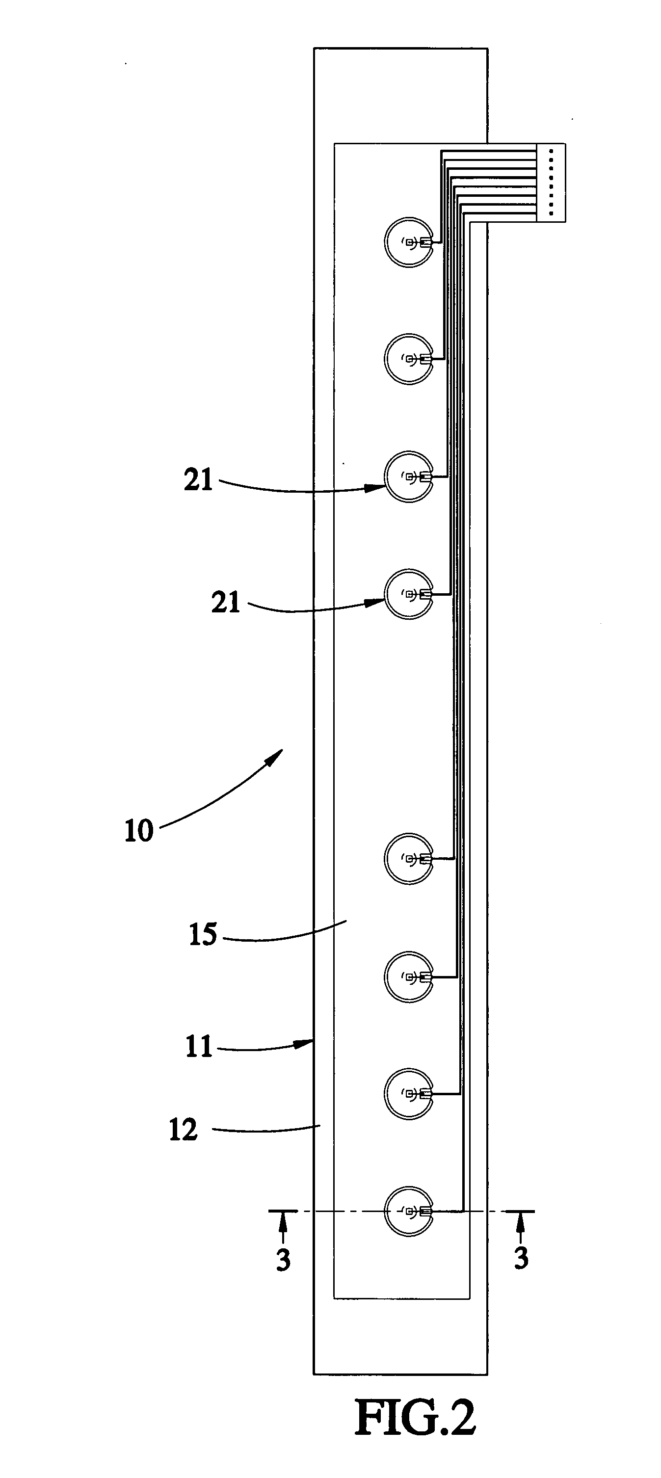
[0019]In practice operation of the first embodiment, an electronic driving device is connected to the circuit board 15 and the substrate 12. The cathodes 232 of the LED chips 23 are electrically connected to the substrate 12 through the wire 24 to form a common cathode that an electrical circuit board is formed. A power supply (not shown) is connected to the LED chips 23 through the wire 24 and the substrate 12 to make them lighting. A heat, which is generated by the LED chips 23 when they are lighting, will be transmitted to the substrate directly, and then transmitted to the fins 13 for heat transmission by the heat sink 11 with a grater size. This provides a high heat transmission efficiency for the LED chips 23.

[0020]As shown in FIG. 4, a combination assembly of LED and heat sink 30 of the second preferred embodiment of the present invention, which is similar to the assembly 10 of the first embodiment, except that:

[0021]Each of LED chips 43 has an anode 431 and a cathode 432 at ...

third embodiment

[0026]In addition, the third embodiment also may provide a lid-like package device 65′, as shown in FIG. 6, which has the same function of the encapsulant package device as described above.

[0027]In conclusion, the advantages of the present invention are:

[0028]Higher performance of heat transmission: to compare with the prior art, the present invention has no intermediate between the LED chips and the heat sink, so that the present invention has less heat transmission resistance. The present invention provides the LED chips mounted on the heat sink directly or provides a heat transmission base, which has a high heat transmission efficiency, between the LED chips and the heat sink that the heat of the LED chips may be transmitted to the heat sink directly or through the heat transmission base for heat transmission by the great size of the heat sink that has a greater performance of heat transmission than the prior art.


PUM


Abstract

A combination assembly of LED and heat sink includes a heat sink having a substrate and a plurality of fins, a circuit board provided on the substrate and at least one LED unit provided on the heat sink and electrically connected to the circuit board. The heat of the LED unit may be transmitted to the heat sink directly for heat transmission. The present invention has a greater heat transmission efficiency.

Description

BACKGROUND OF THE INVENTION[0001]1. Field of the Invention[0002]The present invention relates generally to a light emitting diode (LED), and more particularly to a combination assembly of LED and heat sink, which has a greater performance in heat transmission.[0003]2. Description of the Related Art[0004]In present days, the high luminance LED produces high heat, and there is no fine solution to fix it yet.[0005]U.S. Pat. No. 5,173,839 provides a heat transmission technique of a LED display. It provides a stack of a belt, an aluminum block, a belt and a heat sink under a LED chip to transmit the heat out. However, this technique provides three intermediates between the LED chip and the heat sink, which is the one performing heat transmission, that make the heat transmission rate is poor because the intermediates cause a greater heat resistance.[0006]Taiwan Patent no. M295889 provides another heat transmission technique of LED. It provides a LED on a heat pipe. The LED includes a LED ...

Claims


Application Information

Patent Timeline
Patent Type & Authority Applications(United States)
IPC IPC(8): H05K7/20H01L33/48H01L33/54H01L33/56H01L33/62H01L33/64
CPCH01L2224/48247F21V29/763H01L2224/49107H01L2224/73265F21V29/004F21Y2101/02H01L33/648H05K1/021H05K1/182H05K3/0061H05K7/20509H05K2201/10106H01L2224/48465H01L2924/00F21Y2115/10F21V29/503
Inventor LAI, YAW-HUEY
Owner TAI SOL ELECTRONICS
Why Eureka
Try Eureka