Fuel reformer using radiation

Inactive Publication Date: 2008-07-17
SAMSUNG SDI CO LTD
View PDF3 Cites 26 Cited by
  • Summary
  • Abstract
  • Description
  • Claims
  • Application Information

AI Technical Summary

Benefits of technology

[0008]It is an object of the present invention to provide a fuel reformer capable of lowering the operating temperature of a heater, preventing the deterio

Problems solved by technology

As such, in the fuel reformer, much of the heat of the heater is absorbed into the inner wall, causing problems in that the heat

Method used


Image

  • Fuel reformer using radiation
  • Fuel reformer using radiation
  • Fuel reformer using radiation

Examples


Embodiment Construction

[0016]Hereinafter, preferred embodiments of the present invention, wherein a person having ordinary skill in the art can easily carry out the present invention, will be described in detail with reference to the accompanying drawings.

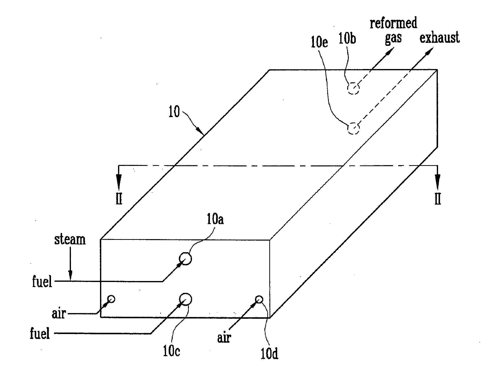
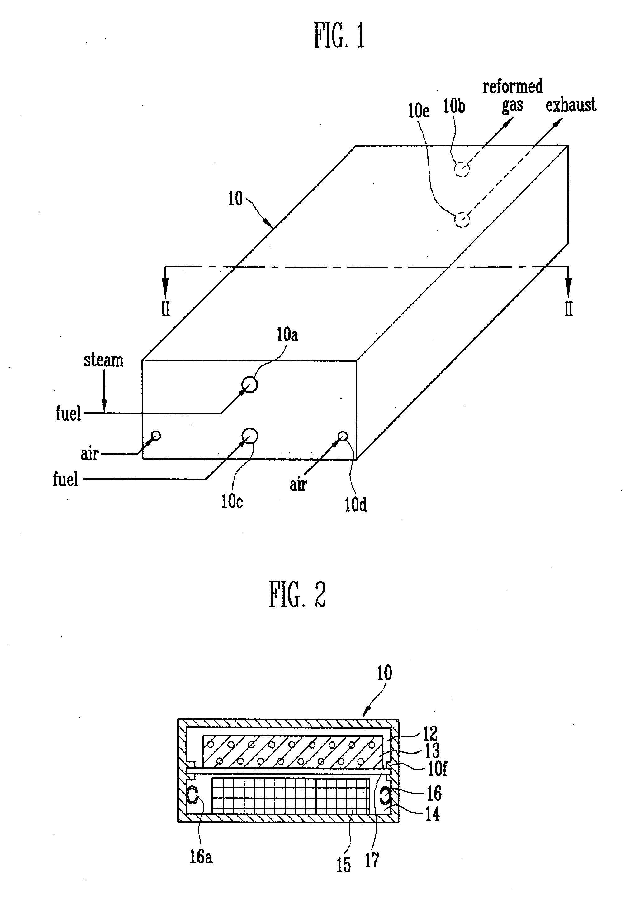
[0017]FIG. 1 is a schematic perspective view of a fuel reformer according to one embodiment of the present invention, and FIG. 2 is a transverse cross-sectional view of the fuel reformer taken along line II-II as shown in FIG. 1.

[0018]Referring to FIGS. 1 and 2, the fuel reformer 10 of the present invention is an apparatus for reforming hydrocarbon fuel to generate hydrogen gas. The fuel reformer 10 includes a reforming reactor 12 having a reforming catalyst 13 therein. Since the reforming reaction using a catalyst is an endothermic reaction, the reforming reactor 12 needs heat for initiating the reaction. Therefore, the fuel reformer 10 includes a heater 14 for supplying heat to the reforming reactor 12. In particular, the fuel reformer 10 of the presen...


PUM


Abstract

A fuel reformer using radiation comprises: a reforming reactor including a reforming catalyst for shifting fuel into a desired substance; a heater for supplying heat to the reforming catalyst; and a transparent inner wall positioned between the reforming reactor and the heater. With the present invention, the heat energy of the heater is transferred to the reforming catalyst in a radiation form so that the thermal efficiency of the fuel reformer can be improved.

Description

CLAIM OF PRIORITY[0001]This application makes reference to, incorporates the same herein, and claims all benefits accruing under 35 U.S.C. §119 from an application for FUEL REFORMER USING RADIATION earlier filed in the Korean Intellectual Property Office on the 12 of Jan. 2007 and there duly assigned Serial No. 2007-4000.BACKGROUND OF THE INVENTION[0002]1. Technical Field[0003]The present invention relates to a fuel processor and, more particularly to a high efficient fuel reformer capable of efficiently using radiation of a heater by including a transparent inner wall.[0004]2. Related Art[0005]A fuel processor is an apparatus for shifting fuel into a desired substance, and is commonly called a “fuel reformer”. A fuel reformer for a fuel cell generates hydrogen from a hydrocarbon fuel, and includes a reforming reactor for performing a reforming catalyst reaction in a high temperature and a heater for supplying heat to the reforming reactor. The reforming catalyst reaction is made at...

Claims


Application Information

Patent Timeline
IPC IPC(8): B01J19/02
CPCB01J8/0465C01B2203/1247B01J2208/00504B01J2219/1923C01B3/323C01B3/384C01B3/48C01B2203/0233C01B2203/0283C01B2203/0288C01B2203/044C01B2203/047C01B2203/0811C01B2203/1058C01B2203/1064C01B2203/107C01B2203/1076C01B2203/1223C01B2203/1235B01J2208/00309C01B3/38C01B3/26
Inventor AHN, JIN-GOOKIM, JU-YONGLEE, YONG-KULHAN, MAN-SEOKLEE, SUNG-CHULKIM, JUN-SICLEE, CHAN-HO
Owner SAMSUNG SDI CO LTD
Why Eureka
Try Eureka