
Magnetic microparticle-packing unit, microfluidic device including the same, and immunoassay method using the microfluidic device

a microfluidic device and magnetic technology, applied in the field of magnetic microparticle packaging units, can solve the problems of reducing the efficiency of immune reactions, difficulty in fabricating a structure to contain microparticles, and increasing the gap between the packed microparticles

Inactive Publication Date: 2008-07-17
SAMSUNG ELECTRONICS CO LTD
View PDF11 Cites 30 Cited by
  • Summary
  • Abstract
  • Description
  • Claims
  • Application Information

AI Technical Summary

Benefits of technology

[0015]In more details the shell may be formed of any one material selected from the group consisting of styrenes agarose, dextran, and polyethylene glycol (PEG). The surface of the shell may be modified such that predetermined biomolecules are specifically bound ...

Problems solved by technology

When a microfluidic device is packed with microparticles of which a diameter is as small as those commercially available, it is difficult to fabricate a structure to contain the microparticles.
On the other hand, the use of larger microparticles can reduce the pressure loss, but the gap between the packed microparticles is increased, lowering the efficiency of an immune reaction.

Method used


Image

  • Magnetic microparticle-packing unit, microfluidic device including the same, and immunoassay method using the microfluidic device
  • Magnetic microparticle-packing unit, microfluidic device including the same, and immunoassay method using the microfluidic device
  • Magnetic microparticle-packing unit, microfluidic device including the same, and immunoassay method using the microfluidic device

Examples


Embodiment Construction

[0023]Hereinafter, the present invention will now be described in detail with reference to the accompanying drawings.

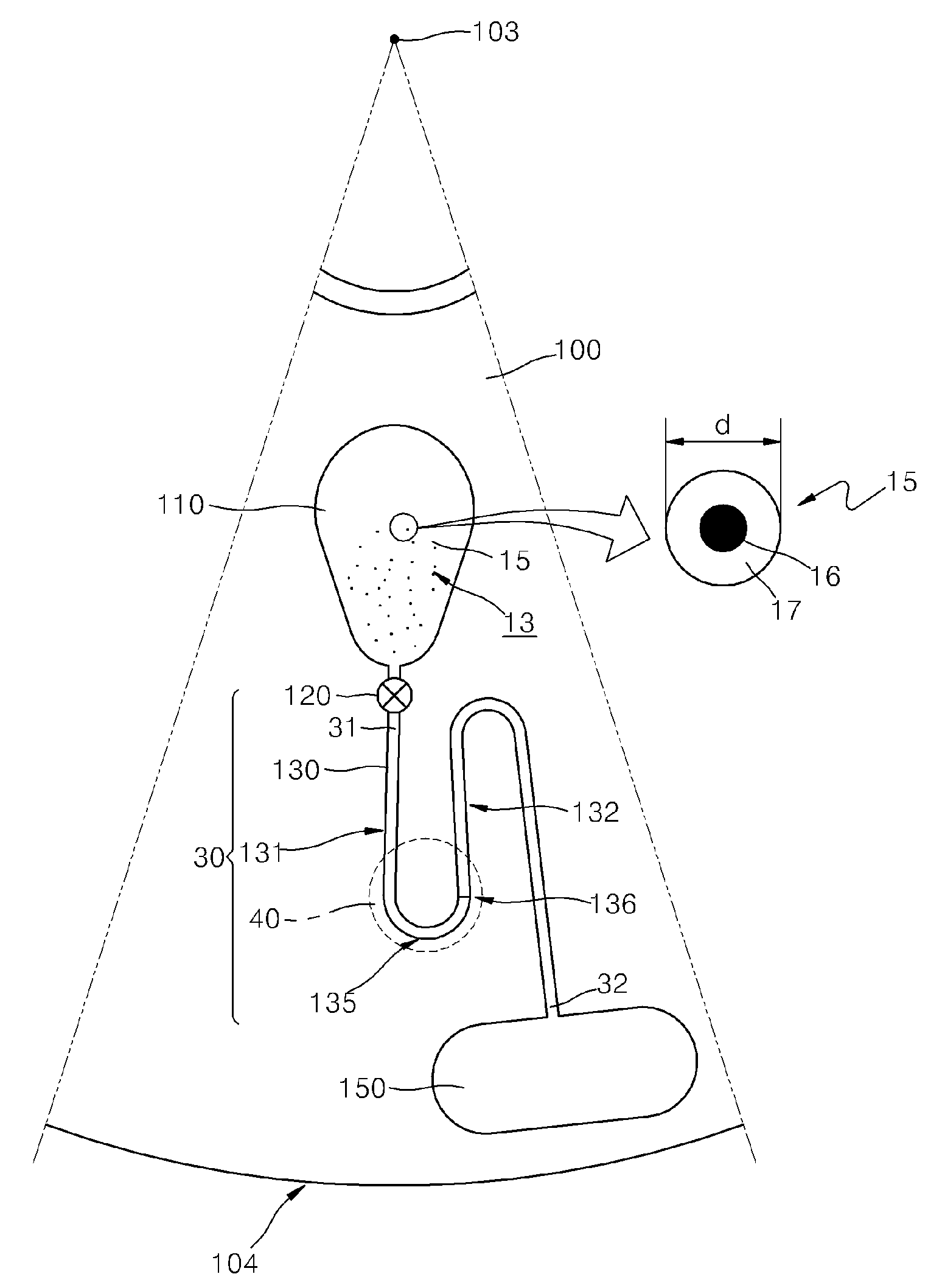
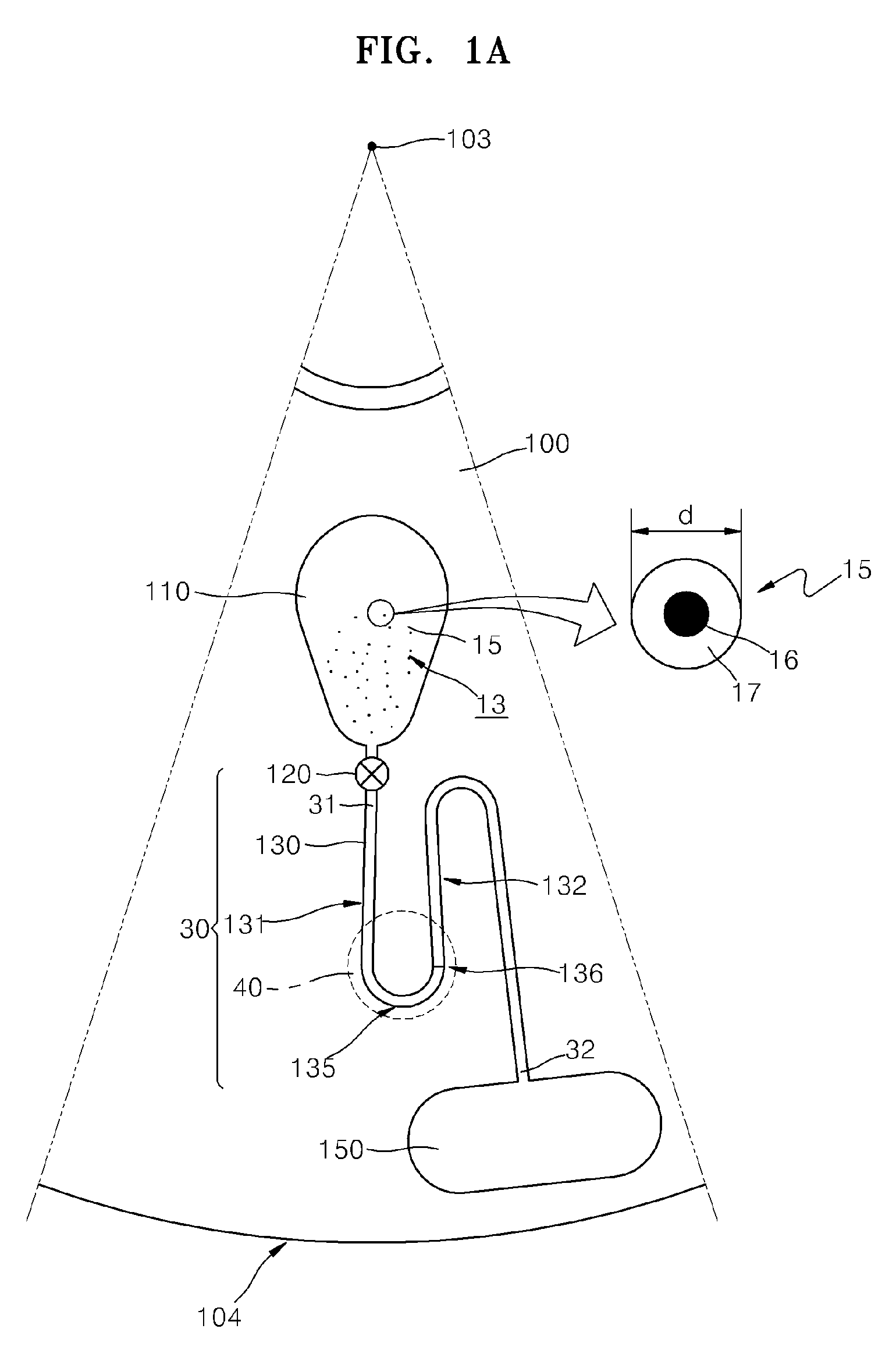
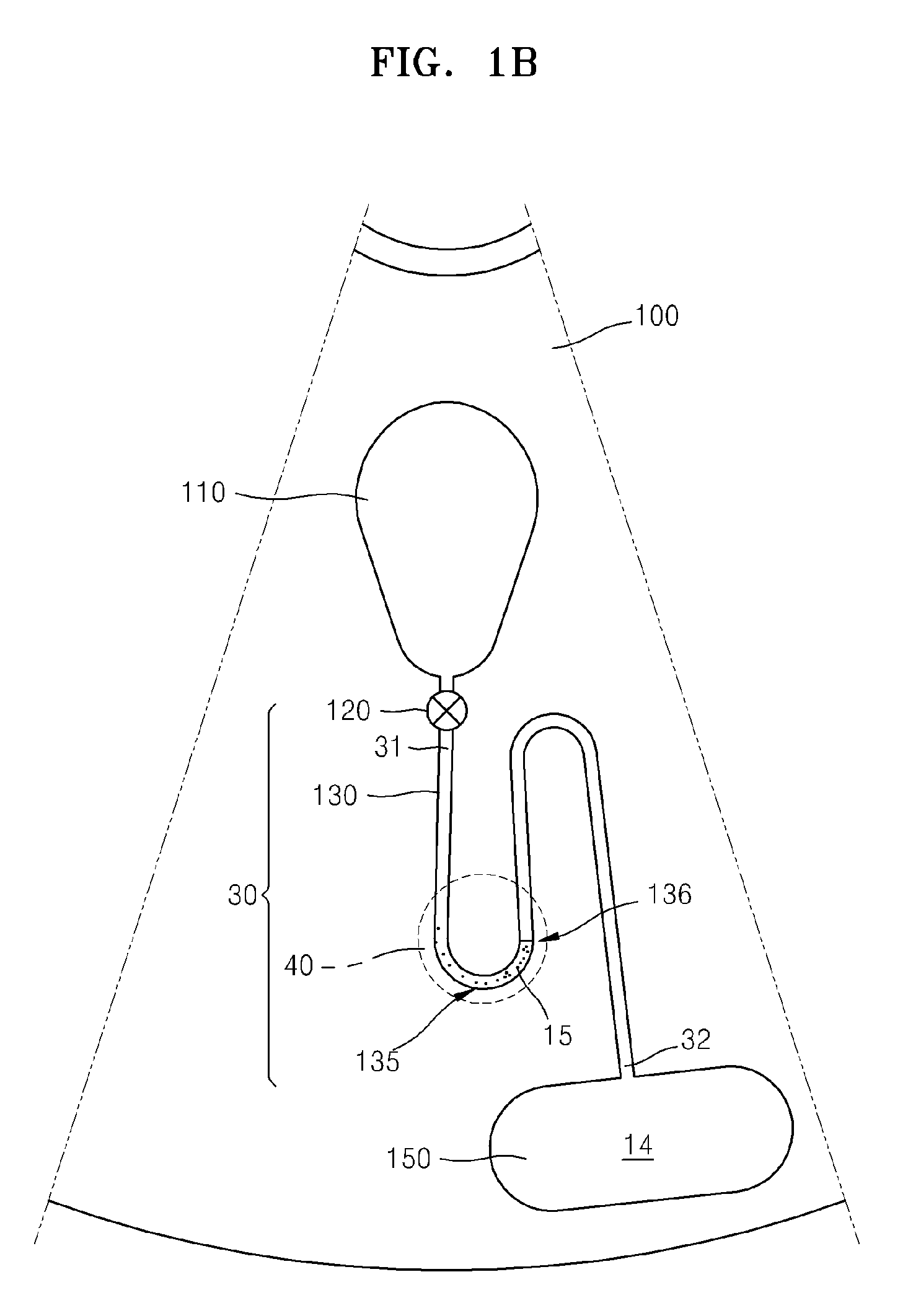
[0024]FIGS. 1A and 1B are plan views of a microfluidic device before and after packing magnetic microparticles, respectively, according to an exemplary embodiment of the present invention.

[0025]Referring to FIGS. 1A and 1B, the microfluidic device includes a rotating plate 100. The rotating plate 100 has a rotation center 103 and a periphery 104. A magnetic microparticle-packing unit 30 according to an embodiment of the present invention is disposed on the rotating plate 100. In one exemplary embodiment, the rotating plate 100 has an upper layer and a lower layer, and the upper and lower layers are joined together to define channels, chambers, flow passages, valves and others, which are described below. The structures may be formed in one of the upper and lower layers. The rotating plate 100 is an example of a rotary body that controllably rotates, but the present inv...


PUM

PropertyMeasurementUnit
Diameteraaaaaaaaaa
Centrifugal forceaaaaaaaaaa
Flow rateaaaaaaaaaa

Abstract

A magnetic microparticle-packing unit using centrifugal force, a microfluidic device including the same, and an immunoassay method using the microfluidic device are provided. The magnetic microparticle-packing unit includes a rotary body controllably rotating; a microfluidic channel which includes a curved portion in which the microfluidic channel first extends away from the rotation center of the rotary body and then turns toward the rotation center of the rotary body.

Description

CROSS-REFERENCE TO RELATED PATENT APPLICATION[0001]This application claims the benefit of Korean Patent Application No. 10-2006-0082941, filed on Aug. 30, 2006, in the Korean Intellectual Property Office, the disclosure of which is incorporated herein in its entirety by reference.BACKGROUND OF THE INVENTION[0002]1. Field of the Invention[0003]The present invention relates to a magnetic microparticle-packing unit using centrifugal force, a microfluidic device including the same, and an immunoassay method using the microfluidic device, and more particularly, to a microfluidic device which can effectively pack magnetic microparticles and an immunoassay method using the microfluidic device.[0004]2. Description of the Related Art[0005]An immunoassay is a test including marking any one or both of an antigen and an antibody with a radioisotope, a chemiluminescent material, or the like and measuring the existence of the antigen or the antibody through an antigen-antibody reaction. A method ...

Claims


Application Information

Patent Timeline
IPC IPC(8): G01N33/553B01J19/00G01N33/552
CPCB01L3/50273B01L3/502738B01L3/502761G01N33/5304B01L2400/0409B01L2400/043B01L2300/0806
Inventor CHO, YOON-KYOUNGLEE, BEOM-SEOKLEE, JEONG-GUN
Owner SAMSUNG ELECTRONICS CO LTD
Learn More