
Wireless communications system implementing a plurality of wireless communications schemes with handover capability

Inactive Publication Date: 2008-07-17
PANASONIC CORP
View PDF17 Cites 4 Cited by
  • Summary
  • Abstract
  • Description
  • Claims
  • Application Information

AI Technical Summary

Benefits of technology

[0010]It is an object of the present invention to provide a wireless communications system implementing a plurality of wireless communications schemes with handover capability, wherein it is possible to reduce the size and the cost of the system.
[0011]The present invention provides a communications system with two different wireless communications schemes, wherein sections implementing each communications scheme are classified into a section for the dedicated function and that for the common function, and the dedicated function sections of the communications schemes monitor each other, whereby it is possible to efficiently use the common function section by switching the use of the common function section between the communications schemes. This eliminates the need for providing separate wireless interfaces for the two schemes, and makes it possible to reduce the size and the cost of the system.

Problems solved by technology

Accommodating a plurality of different communications schemes as described above makes it difficult to reduce the size and cost of the communications device.

Method used


Image

  • Wireless communications system implementing a plurality of wireless communications schemes with handover capability
  • Wireless communications system implementing a plurality of wireless communications schemes with handover capability
  • Wireless communications system implementing a plurality of wireless communications schemes with handover capability

Examples


embodiment 1

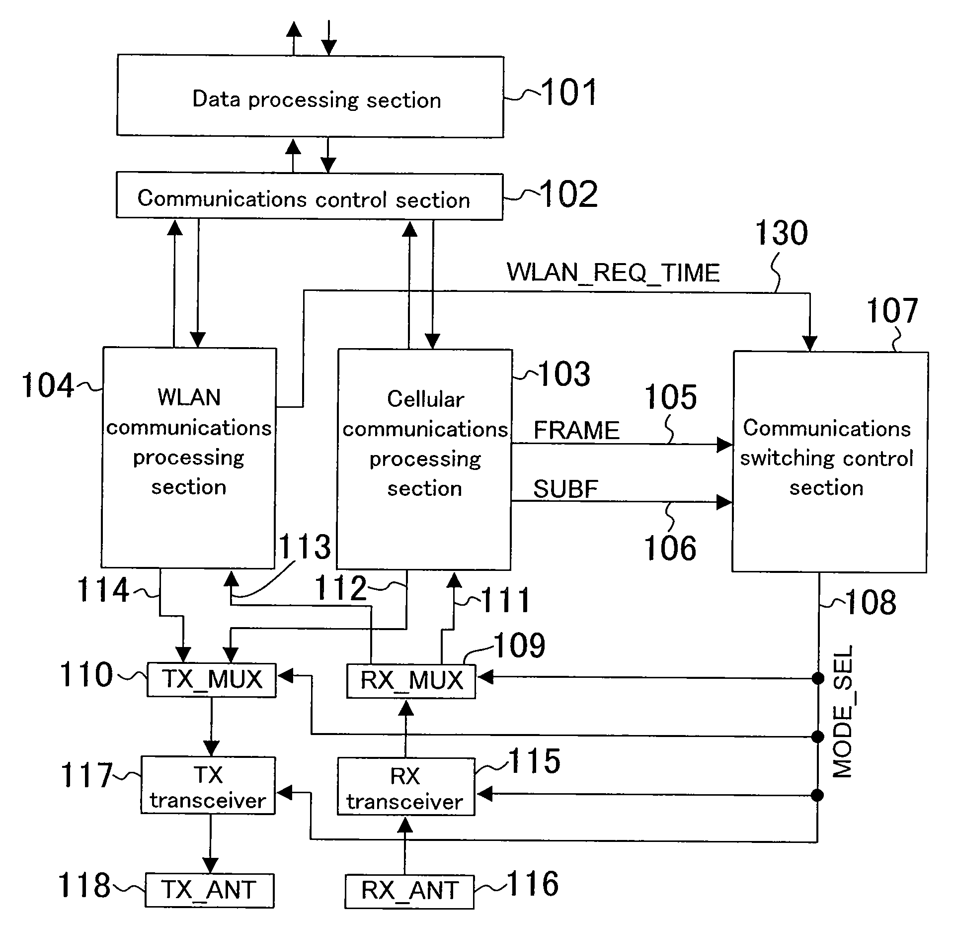
[0063]FIG. 1 is a block diagram showing a configuration of a wireless communications system according to Embodiment 1 of the present invention.

[0064]In the wireless communications system of FIG. 1, a data processing section 101 performs a data process, an IP (internet protocol) process, etc., for enabling the exchange of the communications data with applications.

[0065]A communications control section 102 exchanges data between one of communications processing sections 103 and 104 of which the communications scheme is being currently selected and the data processing section 101. Herein, two types of communications schemes can be selected, i.e., the cellular scheme capable of communications even under moving environments, and the wireless LAN scheme capable of high-speed communications under stationary environments.

[0066]The cellular communications processing section 103 has a function of converting and modulating data input from the communications control section 102 according to the...

embodiment 2

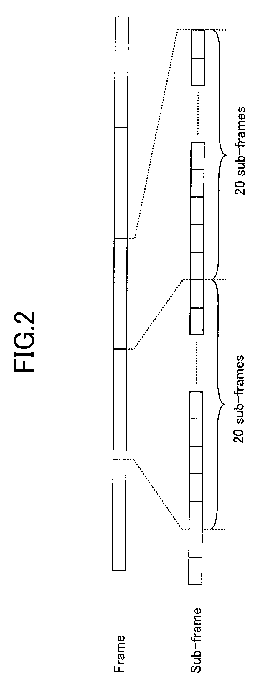
[0087]FIG. 7 is a block diagram showing a configuration of a wireless communications system according to Embodiment 2 of the present invention. This block diagram is similar to that of FIG. 1 except that a wireless LAN communications operation signal (hereinafter, “WLAN_ACT”) 131 is added. WLAN_ACT 131 is a signal indicating that wireless LAN is in a transmitting / receiving operation. WLAN_ACT 131 is HIGH while wireless LAN is in a communications operation, and is LOW while wireless LAN is not in a communications operation. With a series of communications operations such as where an acknowledge signal is received after completion of transmission, this signal is HIGH throughout all the periods of transmission, reception stand-by and reception.

[0088]The operation of the wireless communications system having such a configuration will be described with reference to FIG. 8. In the figure, sub-frames are numbered. Note that a frame includes 20 sub-frames, which are received successively, f...

embodiment 3

[0089]FIG. 9 is a block diagram showing a configuration of a wireless communications system according to Embodiment 3 of the present invention. In this figure, reference numeral 132 denotes a signal indicating that wireless LAN is only requesting the receiving operation (hereinafter, “RX_ONLY”). Reference numeral 133 denotes a transmission scheme switching signal of the receiving side (hereinafter, “RX_MODE_SEL”). Reference numeral 134 denotes a transmission scheme switching signal of the transmitting side (hereinafter, “TX_MODE_SEL”). FIG. 9 is similar to the block diagram of FIG. 7, except that RX_ONLY 132, RX_MODE_SEL 133 and TX_MODE_SEL 134 are added and MODE_SEL 108 is deleted.

[0090]The operation of the wireless communications system having such a configuration will be described with reference to FIG. 10. In the figure, sub-frames are numbered. Note that a frame includes 20 sub-frames, which are received successively, from the first sub-frame to the twentieth sub-frame. In FIG....


PUM


Abstract

A wireless communications system includes: a first communications processing section for implementing a dedicated communications function that is only for the first wireless communications scheme; a second communications processing section for implementing a dedicated communications function that is only for the second wireless communications scheme; a shared transceiver section shared by the first communications processing section and the second communications processing section; a scheme selection section for selectively inputting a signal from the first communications processing section or a signal from the second communications processing section to the shared transceiver section; and a communications switching control section for indicating, to the scheme selection section, a scheme to be selected. The communications switching control section determines a switching timing based on frame and sub-frame information from the first communications processing section in an operation of switching from the first wireless communications scheme to the second wireless communications scheme or an operation of searching for a communications target station using the second wireless communications scheme.

Description

CROSS REFERENCE TO RELATED APPLICATION[0001]This application claims priority under 35 U.S.C. §119 on Patent Application No. 2007-4293 filed in Japan on Jan. 12, 2007 the entire contents of which are hereby incorporated by reference.BACKGROUND OF THE INVENTION[0002]The present invention relates to a wireless communications system implementing a plurality of wireless communications schemes with handover capability.[0003]A conventional mobile communications terminal may have two types of wireless communications means, i.e., cellular and wireless LAN, in which case the two communications means can be switched from one to another.[0004]A cellular terminal can communicate with others while moving around at a high speed and over a wide area outside, but the transmission speed is as low as about 10 Mbps even with third-generation mobile telephones.[0005]Wireless LAN is defined in the IEEE (Institute of Electrical and Electronics Engineers) 802.11 series, and is mainly used to connect to a n...

Claims


Application Information

Patent Timeline
IPC IPC(8): H04M1/00H04W88/06
CPCH04W88/06H04B1/406
Inventor NAGAO, AKIFUMIIRIE, MASATAKAMAKIMOTO, SATOSHINAGASAWA, YUKIYOSHIHATAKEYAMA, TAKESHI
Owner PANASONIC CORP
Features
  • Generate Ideas
  • Intellectual Property
  • Life Sciences
  • Materials
  • Tech Scout
  • Unparalleled Data Quality
  • Higher Quality Content
  • 60% Fewer Hallucinations
Learn More