Device for osteosynthesis

a technology of osteosynthesis and device, applied in the field of osteosynthesis, can solve the problems of inability to lock the screw, and achieve the effects of reducing the cross section of the through hole, compressing the bushing, and reducing the cross section

Inactive Publication Date: 2008-07-17
SYNTHES USA
View PDF99 Cites 21 Cited by
  • Summary
  • Abstract
  • Description
  • Claims
  • Application Information

AI Technical Summary

Benefits of technology

[0010]In one particular embodiment, the cross section of the through hole formed in the osteosynthetic device, which, in a preferred embodiment includes a bone plate, is polygonal, preferably hexagonal, so that said through hole has the form of a prism, preferably a hexagonal prism. In the case of the hexagonal embodiment, the bone screw may be simultaneously moved in three planes within the hexagonal through hole, making it possible to adjust and fix the screw at any desired angle. Said angle is only limited by the plate thickness and by the abutment of the bushing on the reduced cross section. It is of course also possible to use bone plates having a plurality of through holes.
[0016]The surface of the bushing, preferably in the area of its peripheral, outer surface, is suitably roughened, e.g. by means of grit blasting. The through hole formed in the bone plate may correspondingly be roughened, e.g. by means of grit blasting. However, the surface of the bushing, preferably in the area of its peripheral, outside face, may also be provided with a macrostructured portion, e.g. in the form of peripheral ridges. The through hole may then be correspondingly provided with a macrostructured portion, e.g. in the form of peripheral ridges. The advantage of this configuration lies in the positive engagement between the bushing and the bone plate which is thus achievable.
[0017]In another specific embodiment, the through hole formed in the osteosynthetic device, which, in a preferred embodiment includes a bone plate, tapers towards the bottom surface and preferably also towards the top surface, thus resulting in reduced cross sections which prevent the bushing from falling out or from being pressed out. Suitably, the reduced cross section of the through hole and the compressibility of the bushing are selected adequately so that it is still possible to introduce the compressed bushing into the through hole.
[0021]The bone screws to be introduced into the bushing preferably have a conical screw head which is provided with an external screw thread. The advantage of this configuration is that the spreading and the locking of the bushing may thus be realised in a single step.

Problems solved by technology

Consequently, a locking of the screw would not be possible.

Method used


Image

  • Device for osteosynthesis
  • Device for osteosynthesis
  • Device for osteosynthesis

Examples


Embodiment Construction

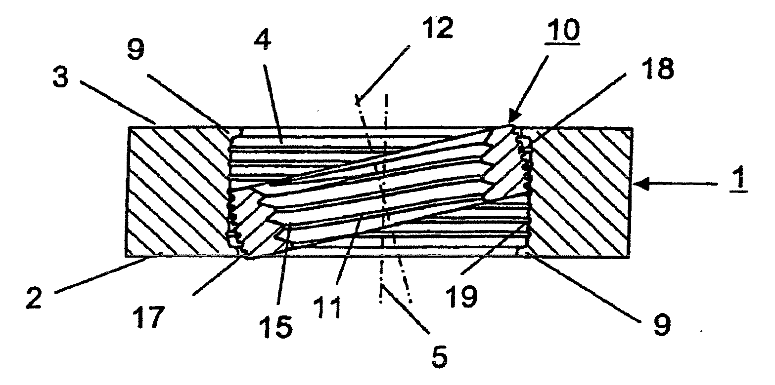
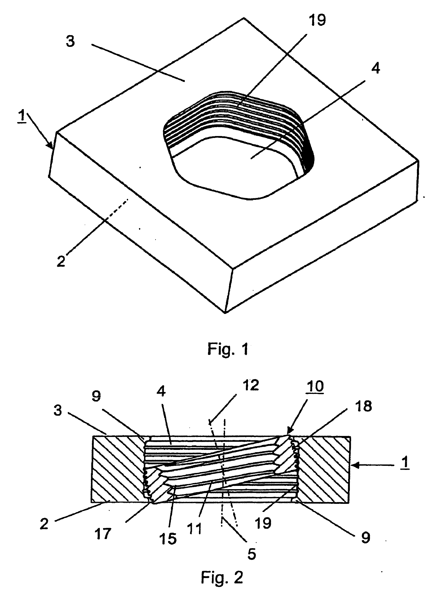
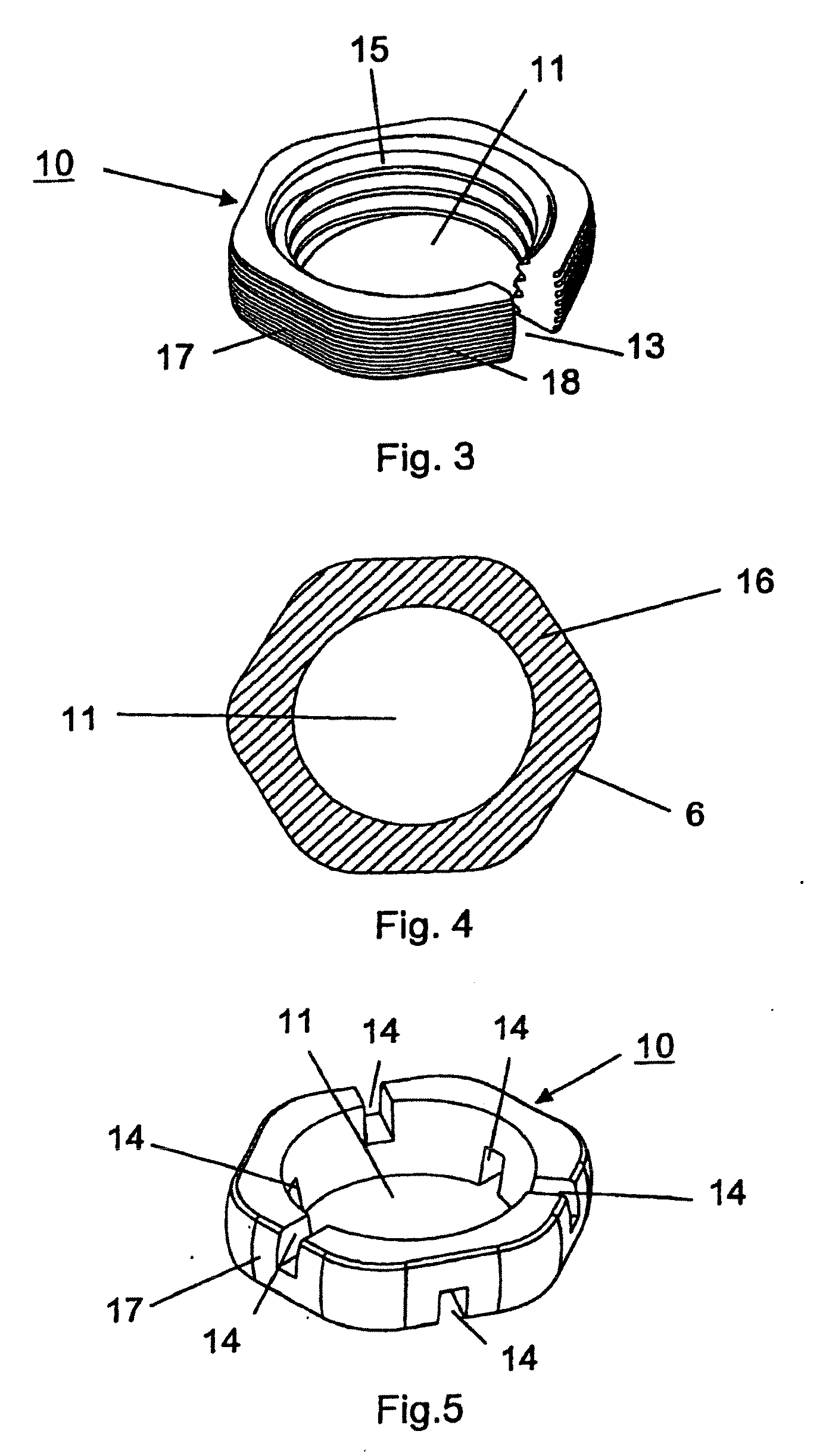
[0032]The device for osteosynthesis represented in FIGS. 1 to 4 consists of a bone plate 1 including a bottom surface 2 designed to bear against the bone, a top surface 3, and a through hole 4 connecting the bottom surface 2 with the top surface 3, designed to receive a multiaxially adjustable bushing 10 for a bone screw 20 (FIG. 8), the through hole 4 having a central axis 5. The bushing 10 (FIG. 3) insertable into the through hole 4 includes a central bore 11 designed to receive the bone screw 20 (FIG. 8), the bore 11 having a longitudinal axis 12, as well as a peripheral outside face 17 designed to be in contact with the through hole 4.

[0033]The bushing 10 has a continuous slot 13 so as to be radially compressible and radially expansible. The through hole 4 of the bone plate 1 is provided, toward the bottom surface 2 and toward the top surface 3 thereof, with a reduced cross section 9 so as to prevent the bushing 10 from falling out or from being pressed out. Suitably, the reduce...


PUM


Abstract

A device for osteosynthesis that includes a fixation element having at least one through hole designed to receive a pivotable bushing for a bone screw. The through hole has a central axis and a cross-section extending orthogonally to the central axis defined by two incomplete semicircles connected to each other by at least two non-circular cut outs forming grooves in the fixation element. The device also includes at least one bushing insertable in the through hole. The bushing has top and bottom surfaces, a longitudinal axis, a central bore designed to receive a bone screw, and a peripheral outside face having at least two outwardly extending protrusions defining an axis of rotation of the bushing extending through the protrusions. A cross section of the bushing orthogonal to the longitudinal axis is shaped such that the bushing is pivotable about the axis of rotation defined by the protrusions.

Description

CROSS-REFERENCE TO RELATED APPLICATIONS[0001]The present application is a continuation of co-pending U.S. application Ser. No. 10 / 877,096, filed Jun. 24, 2004, which is a continuation of the U.S. national stage application of International Patent Application No. PCT / CH01 / 00740, filed Dec. 24, 2001, the entire contents of both of which are expressly incorporated herein by reference.FIELD OF THE INVENTION[0002]The invention relates to a device for osteosynthesis, and more particularly, to a fixation device, such as a bone plate, having a polyaxial bushing and screw assembly for securing such a device to bone.BACKGROUND OF THE INVENTION[0003]Assemblies of the present type serve for screwing together elements such as pedicle screws or pedicle hooks in a polyaxial, rigid manner, and are used in particular in the area of the spinal column. However, these assemblies may also be employed for plating in general. Additional fields of application include use in combination with external fixato...

Claims


Application Information

Patent Timeline
Patent Type & Authority Applications(United States)
IPC IPC(8): A61B17/58A61B17/56A61BA61B17/80A61B17/86
CPCA61B17/8695A61B17/8047
Inventor MATHIEU, CLAUDEFRIGG, ROBERTSANER, HARALD
Owner SYNTHES USA
Why Eureka
Try Eureka