Coriolis force gyroscope with high sensitivity

a gyroscope and coriolis force technology, applied in the field of gyroscopes, can solve the problems of reducing the sensitivity of the system, and deviating from a perfectly symmetrical structure, and achieve the effect of high sensitivity

Active Publication Date: 2008-07-24
INNALABS
View PDF4 Cites 1 Cited by
  • Summary
  • Abstract
  • Description
  • Claims
  • Application Information

AI Technical Summary

Problems solved by technology

Since it is difficult to form a low compliance bond between two curved surfaces, the transducers must be sufficiently small to form an essentially flat interface with the curved surface of the annular shell.
The output of the vibration-sensing transducers is limited by their strain capability, so that the sensitivity of the system is limited by signal-to-noise ratio.
The overall structure, therefore, deviates from a perfectly symmetrical structure, since it is extremely difficult to glue the piezoelectric elements with perfect repeatability.

Method used


Image

  • Coriolis force gyroscope with high sensitivity
  • Coriolis force gyroscope with high sensitivity
  • Coriolis force gyroscope with high sensitivity

Examples


Embodiment Construction

[0026]Reference will now be made in detail to embodiments of the present invention, examples of which are illustrated in the accompanying drawings.

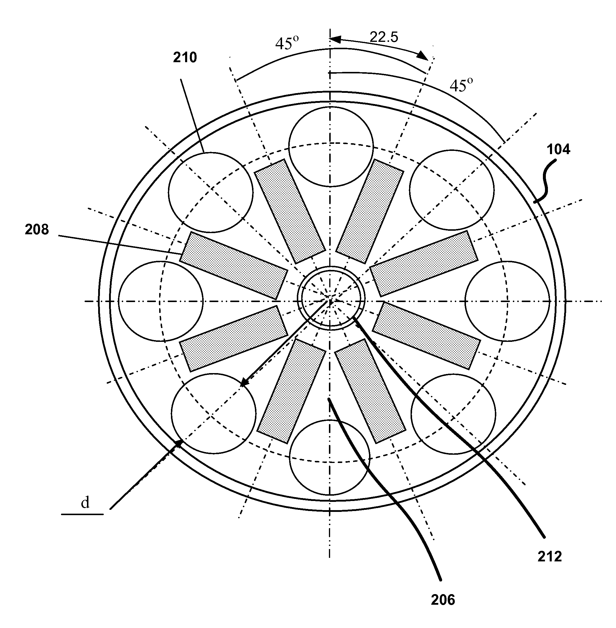
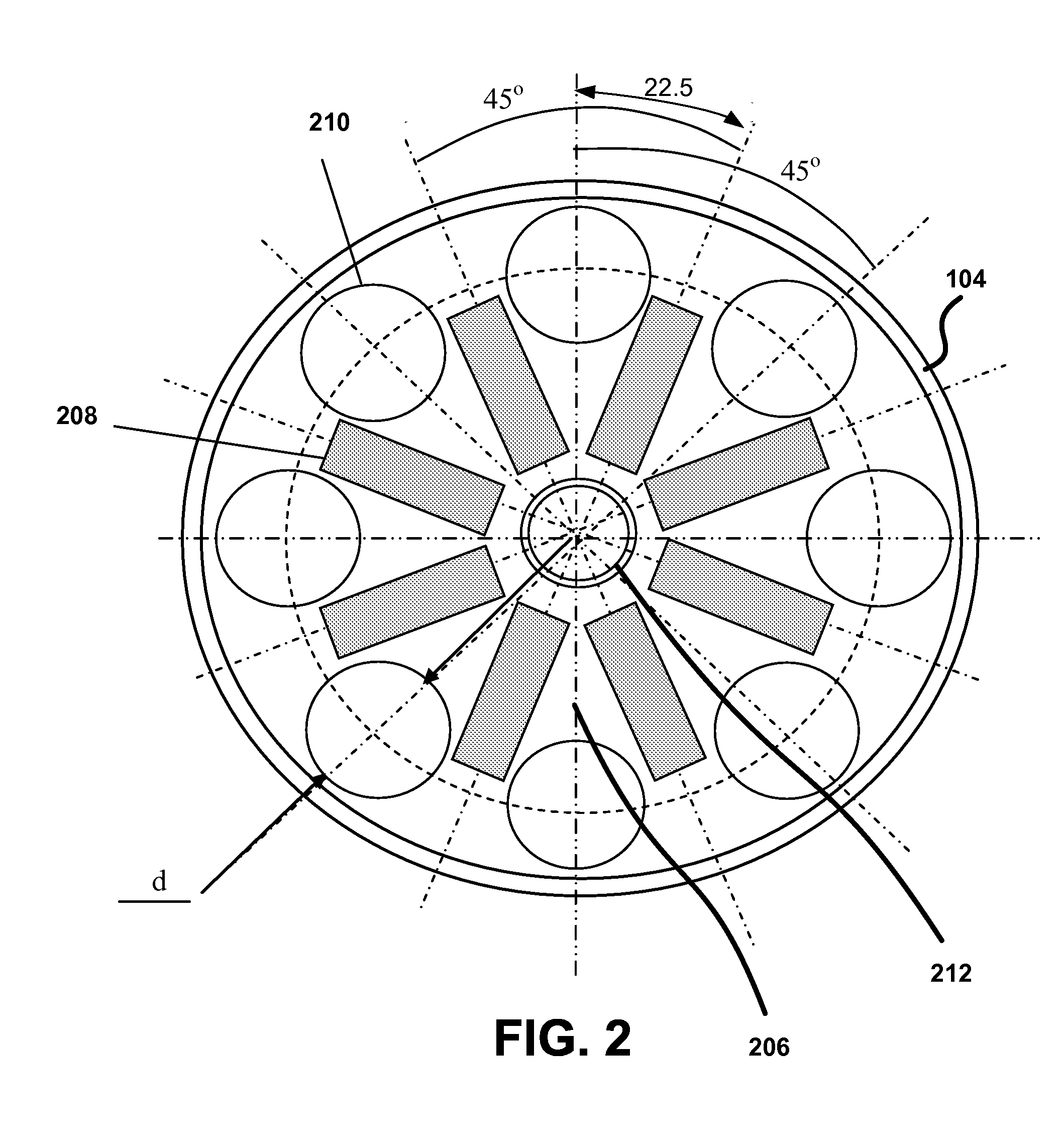
[0027]FIG. 2 illustrates one embodiment of the invention. As shown in FIG. 2, a resonator of a Coriolis force gyroscope, shown in a top plan view, includes a resonator body 104 and a bottom plate 206, which has been modified in a particular way. The bottom plate 206 includes a plurality of openings 210, which are preferably equi-angularly distributed around the periphery of the bottom plate 206. The bottom plate 206, therefore, in effect, has a number of “spokes” (as in wheel spokes). In between the openings 210, a number of piezoelectric elements 208 are placed on the bottom plate. 212 in FIG. 2 designates a mounting hole, which is used to secure the resonator 104.

[0028]The piezoelectric elements 208 act to both vibrate the resonator 104 in its primary mode, and to detect the secondary vibration mode of the resonator 104. It should be no...


PUM


Abstract

A gyroscope includes a substantially cylindrical resonator mounted in a housing, and a bottom plate attached to the resonator. A plurality of openings are arranged circumferentially and equiangularly on the bottom plate. A plurality of piezoelectric elements arranged between the openings on the bottom plate. The number of openings can be anywhere between 2 and 16, with eight openings preferred, with a corresponding number of piezoelectric elements. Preferably, substantially the entire available area of the bottom plate is taken up by the piezoelectric elements. The piezoelectric elements can be inside or outside the resonator.

Description

CROSS REFERENCE TO RELATED APPLICATIONS[0001]This application is a continuation of U.S. patent application Ser. No. 11 / 284,922, filed on Nov. 23, 2005, entitled STEMLESS HEMISPHERICAL RESONATOR GYROSCOPE, which claims priority to Ukrainian Patent Application No. 200505177, filed May 31, 2005, which are incorporated herein by reference in their entiretyBACKGROUND OF THE INVENTION[0002]1. Field of the Invention[0003]The present invention is related to gyroscopes, and more particularly, to gyroscopes having high sensitivity and high signal-to-noise ratio.[0004]2. Background Art[0005]Vibrational gyroscopes have many advantages over conventional gyroscopes of the spinning wheel type. Thus, a vibrational gyroscope is considerably more rugged than a conventional spinning wheel gyroscope, can be started up much more quickly, consumes much less power and has no bearings which could be susceptible to wear.[0006]A wide variety of vibrating members have been employed in previously proposed vibr...

Claims


Application Information

Patent Timeline
Patent Type & Authority Applications(United States)
IPC IPC(8): G01C19/00
CPCG01C19/5691Y10T74/12Y10T29/49002
Inventor CHIKOVANI, VALERY V.YATZENKO, YURI A.KOVALENKO, VLADIMIR A.
Owner INNALABS
Why Eureka
Try Eureka