Shaft with Functional Bodies Such as Camshafts for Internal Combustion Engines, Method of Producing Them and Engines Equipped Therewith

a technology of internal combustion engine and camshaft, which is applied in the field of camshafts, can solve the problems of not being able to fully exploit the advantages of roller bearings, such as lower power loss, and the above-mentioned reasons to use camshafts as pre-assembled units, and achieve the effect of reducing the cost of camshafts and reducing the imbalance of camshafts

Active Publication Date: 2008-07-24
NEUMAYER TEKFOR ENG GMBH
View PDF6 Cites 15 Cited by
  • Summary
  • Abstract
  • Description
  • Claims
  • Application Information

AI Technical Summary

Benefits of technology

[0008]Another object of the invention is to improve, simplify and reduce the cost of assembling engines.
[0029]Another concept of the present invention relates to the design of functional bodies, such as cams for an assembled camshaft in particular. This part of the present invention is based on the object of saving material, reducing the cost of camshafts, and reducing the imbalance in camshafts. This is achieved according to the present invention in that a groove which at least partially penetrates in the axial direction of the cam is introduced in the cam in the area of the cam lobe. This groove may extend continuously through the cam in the axial direction, or it optionally may extend only partially through the cam. The groove—viewed in the direction toward the front side of the cam—may be crescent-shaped and only be introduced from one side, or also from both sides. The groove may also be a continuous, at least approximately circular recess. In this way a significant part of the costly material which is otherwise used in solid cams may be saved.

Problems solved by technology

Therefore, it was not possible for the above-mentioned reasons to use camshafts as pre-assembled units and to exploit the mounting possibilities associated therewith, nor to fully exploit the advantages of roller bearings, such as lower power losses.
The above-mentioned disadvantages also exist for such assembled shafts.

Method used


Image

  • Shaft with Functional Bodies Such as Camshafts for Internal Combustion Engines, Method of Producing Them and Engines Equipped Therewith
  • Shaft with Functional Bodies Such as Camshafts for Internal Combustion Engines, Method of Producing Them and Engines Equipped Therewith

Examples


embodiment 13

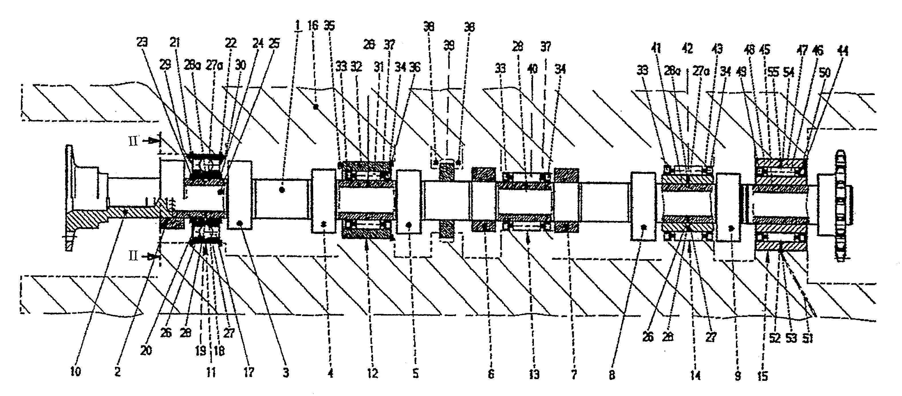
[0039]In a journal embodiment 13 in a camshaft produced as a pre-assembled unit, only the elements of a roller bearing held together by a one-piece cage 37, namely the roller bodies 40, are pre-mounted. The bearing also may be lubricated through a hole 28, and the oil flow may be throttled by corresponding gap seals 33, 34 in the journal 13 in the same way as on the journal 11.

embodiment 14

[0040]In a journal embodiment 14, the pre-assembled unit specifically contains a camshaft and at least undivided elements of a roller bearing, the undivided inner ring 41 pushed or pressed onto the bearing seat and the rollers 42, which are held together by an undivided cage 43. Seals 33, 34 may again be provided laterally of the rollers 42. As in the journal 11, a hole 26 may be provided in the main body 10 for supplying lubricant, together with an annular cavity 27 in the inner ring and a hole 28 in the outer ring. The annular cavity may also be introduced into the shaft main body, however, in the form of the annular chamber 27a, from which the hole 28a opens into the race.

[0041]To form bearings corresponding to the journal identified by reference numeral 15, the camshaft again contains complete roller bearings in the form of the needle bearing 44 having an inner ring 45 pushed or pressed on the shaft body, an outer ring 46, rollers 47, cage 48, and seals 49, 50, which are constru...


PUM


Abstract

A shaft comprising functional elements, such as an assembled camshaft for an internal combustion engine, a method for producing such shafts, and internal combustion engines equipped with such shafts. The functional elements each have a bore and are produced separately from the shaft main body, and the bore is subsequently press fit onto the shaft body to attach the functional element in an axially and rotationally fixed manner. The shaft is also provided with at least one roller bearing that includes at least one undivided roller bearing element which is mounted on the shaft body between two functional elements, for example, by press fitting.

Description

CROSS REFERENCE TO RELATED APPLICATIONS[0001]This application is a continuation of international application no. PCT / DE2006 / 001378, filed Aug. 7, 2006 designating the United States of America and published in German on Feb. 15, 2007 as WO 2007 / 016913, the entire disclosure of which is incorporated herein by reference. Priority is claimed based on Federal Republic of Germany patent application no. DE 10 2005 036 995.2, filed Aug. 5, 2005.BACKGROUND OF THE INVENTION[0002]The present invention relates to shafts having at least one functional body, manufactured separately from the shaft and then fastened on the shaft, such as assembled camshafts, which are mountable inside an internal combustion engine, as well as methods for producing such shafts and internal combustion engines equipped therewith.[0003]Assembled camshafts, as well as methods for their production, in which separately produced cams are fixed on a shaft, are known, for example, from U.S. Pat. No. 6,286,196 (=DE 198 31 333...

Claims


Application Information

Patent Timeline
Patent Type & Authority Applications(United States)
IPC IPC(8): F16H53/00F01L1/04F16C33/10F16C33/58
CPCB24B19/12F01L1/047F01L1/053F01L2001/0476Y10T29/49293F16C3/023F16H53/025Y10T74/2101F01L2103/01F01L2001/0471F01L2001/0475F01L2250/02F01L2810/02F16C33/6677F16C2360/18F01L2303/01
Inventor VOGEL, MANFREDDERSE, MATTHIASBECHTOLD, MATTHIAS
Owner NEUMAYER TEKFOR ENG GMBH
Why Eureka
Try Eureka