Cleaning apparatus and method and computer readable medium
a technology of cleaning apparatus and computer readable medium, which is applied in the direction of cleaning process and apparatus, cleaning using liquids, chemistry apparatus and processes, etc., can solve the problems of contaminated portions touching and contaminating the back surface of the substrate, and the liquid delivery port is not generally rotatabl
- Summary
- Abstract
- Description
- Claims
- Application Information
AI Technical Summary
Benefits of technology
Problems solved by technology
Method used
Image
Examples
first embodiment
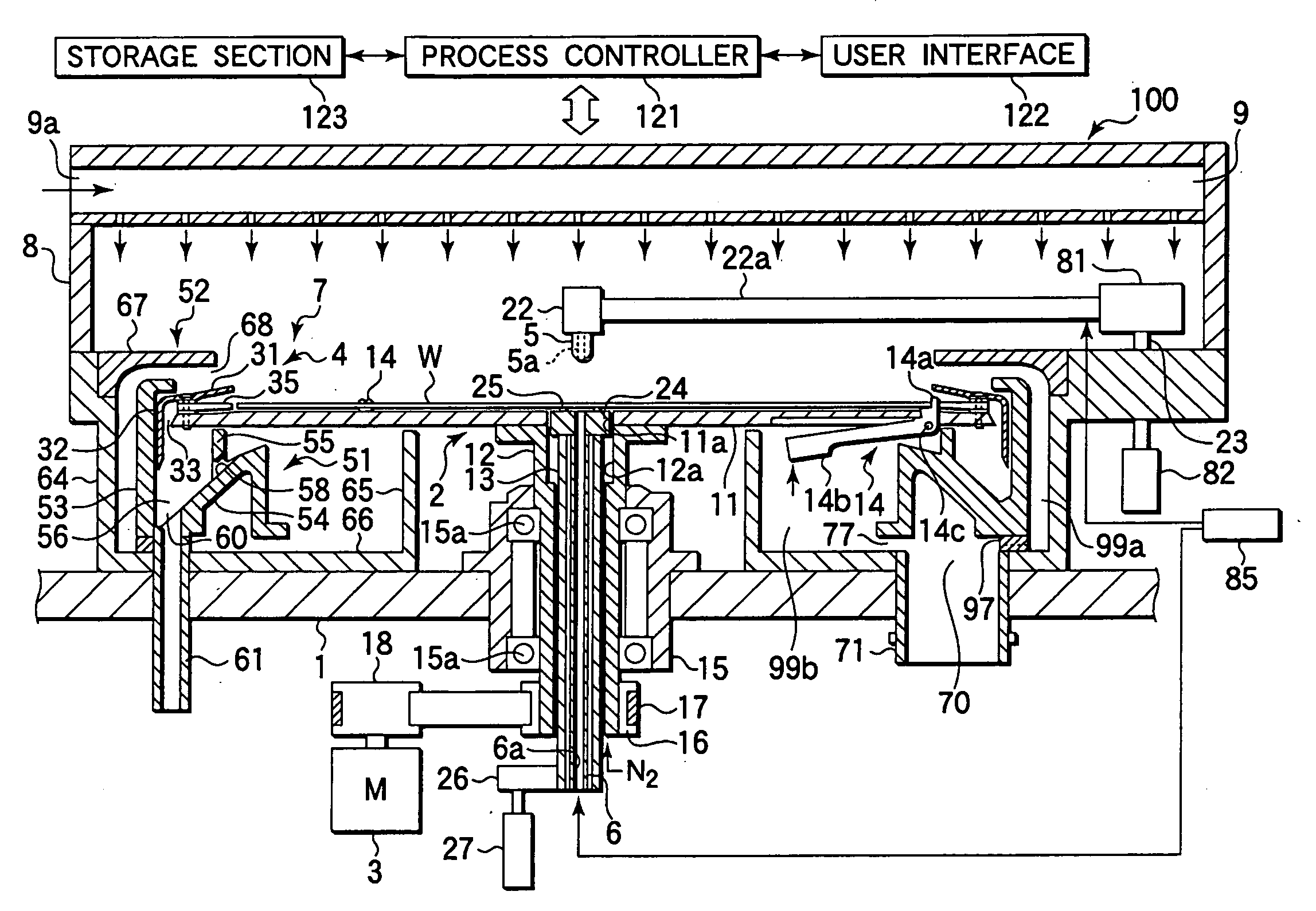
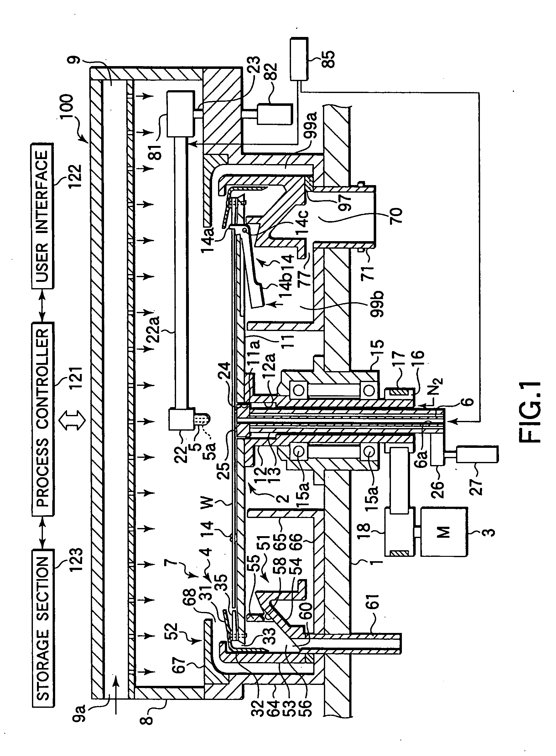
[0061]At first, a cleaning method will be explained with reference to the flow chart shown in FIG. 6 and the schematic views shown in FIGS. 7A to 7H. In this embodiment, cleaning is performed on the front and back surfaces of a wafer W by use of a cleaning liquid, and then cleaning is performed on the liquid delivery plate 24 when a rinsing process is performed. In this embodiment, the following operations for a cleaning process are controlled by the process controller 121 in accordance with a recipe stored in the storage section 123. The following explanation made with reference to FIGS. 6 and 7A to 7H are focused on cleaning performed on the back surface of the wafer W and cleaning performed on the liquid delivery plate 24. However, when a cleaning process using a cleaning liquid and a rinsing process using purified water are performed on the back surface of the wafer W, a cleaning process using a cleaning liquid and a rinsing process using purified water are also performed on th...
third embodiment
[0093]Thereafter, in light of a case where the back surface of the wafer is hydrophilic, a drying gas, such as N2 gas, is spouted from the nozzle hole 6a onto the center of the wafer back surface (STEP 4-11 and FIG. 14K). This is performed as in STEP 3-9 of the third embodiment, because the center of the wafer back surface tends to suffer insufficient drying where the wafer back surface is hydrophilic. Accordingly, a drying gas is spouted onto the center of the wafer back surface to facilitate drying. At this time, the flow rate of the drying gas is preferably set to be 1 to 50 NL / min.
[0094]Then, N2 gas is stopped, and a throwing off and drying operation is performed on the wafer W (STEP 4-12 and FIG. 14L). At this time, the rotation speed of the wafer W is preferably set to be 1,000 to 2,000 rpm.
[0095]In the first to fourth embodiments, the liquid delivery plate 24 is subjected to cleaning by use of a rinsing liquid or purified water. Where the liquid delivery plate 24 should be mo...
fifth embodiment
[0096]FIG. 15 is a flow chart showing the operational flow of a cleaning method according to the present invention. FIGS. 16A to 16H are schematic views for explaining the operation thereof. In this embodiment, the arrangement shown in FIG. 3 is used as a liquid supply mechanism.
[0097]At first, in STEP 5-1 to 5-3 of FIG. 15 shown in FIGS. 16A to 16C, the same operations as those of STEP 1-1 to 1-3 of the first embodiment shown in FIGS. 7A to 7C are performed. In the state of STEP 5-3 shown in FIG. 16C, a liquid film of the cleaning liquid is formed on the back surface of a wafer W. However, at the beginning, the back surface liquid supply nozzle 6 is not filled with liquid, so no liquid film is formed on the liquid delivery plate 24 when the cleaning liquid starts being delivered. Accordingly, delivery of the cleaning liquid is once stopped, so that the back surface liquid supply nozzle 6 is filled with the cleaning liquid (STEP 5-4 and FIG. 16D).
[0098]In this state, delivery of the...
PUM
 Abstract
Description
Claims
Application Information
 - R&D
- Intellectual Property
- Life Sciences
- Materials
- Tech Scout
- Unparalleled Data Quality
- Higher Quality Content
- 60% Fewer Hallucinations
Browse by: Latest US Patents, China's latest patents, Technical Efficacy Thesaurus, Application Domain, Technology Topic, Popular Technical Reports.
© 2025 PatSnap. All rights reserved.Legal|Privacy policy|Modern Slavery Act Transparency Statement|Sitemap|About US| Contact US: help@patsnap.com


