Friction plate for wet multi-plate clutch

a multi-plate clutch and friction plate technology, which is applied in the direction of mechanical actuated clutches, friction linings, couplings, etc., can solve the problems of insufficient implementation of the friction plate and the separator plate, inability to reduce the dragging torque, and inability to prevent the occurrence of a biting in the initial engagement stage. , to achieve the effect of preventing the burning of friction material and preventing the occurrence of a biting

Inactive Publication Date: 2008-07-24
NSK WARNER
View PDF6 Cites 15 Cited by
  • Summary
  • Abstract
  • Description
  • Claims
  • Application Information

AI Technical Summary

Benefits of technology

[0014]In the friction plate of the invention that is configured as has been described above, the dragging torque when the clutch is idle is decreased further, and pores at ends of the pressure molded oil grooves are collapsed, so that oil residing in the friction material is discharged to the friction surface in an initial stage of engagement of the clutch, whereby the occurrence of a biting in the engagement initial stage can be prevented. Furthermore, clearances between the segment pieces constitute through passages of oil for prevention of burning of the friction material.

Problems solved by technology

In conventional friction plates, the discharge of oil from friction surfaces was not sufficiently performed, and therefore, the demand for further reduction of dragging torque could not be satisfied.
In particular, in a low rotational speed region, the discharge of oil left interposed between the friction plates and the separator plates could not be implemented sufficiently, and therefore, the dragging torque could not be decreased.

Method used


Image

  • Friction plate for wet multi-plate clutch
  • Friction plate for wet multi-plate clutch
  • Friction plate for wet multi-plate clutch

Examples


embodiments

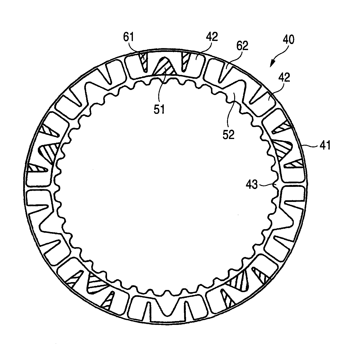
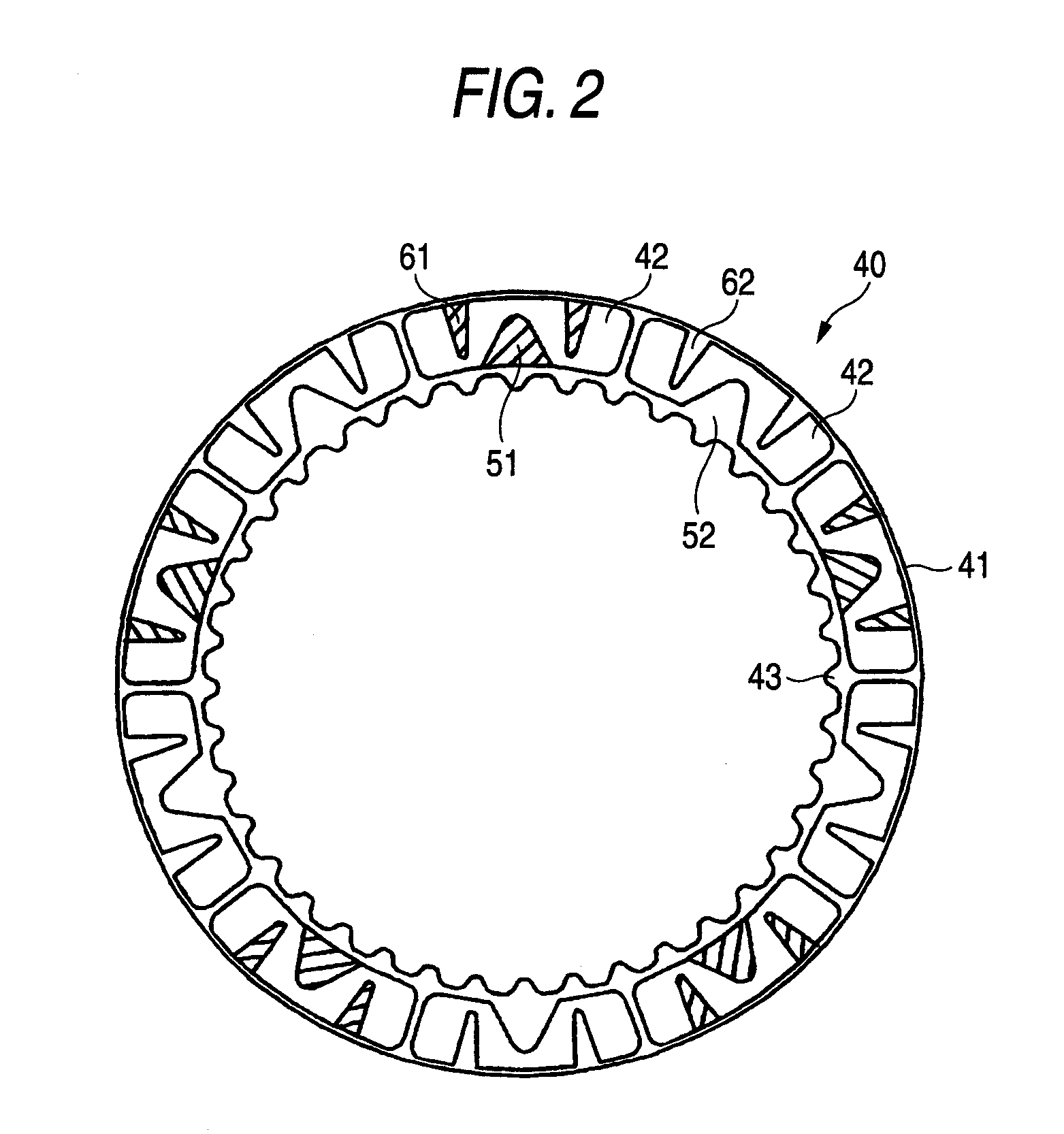
[0024]FIGS. 2 to 7 are front views of respective embodiments of friction plates 40 according to the invention. Reference numerals in those figures are common thereover, and reference numeral 41 denotes a core plate, 42 a segment piece, and 43 a spline tooth which fit in a hub 22.

[0025]In addition, grooves shaded with oblique lines indicate that they are formed through pressure molding.

[0026]FIG. 2 is a front view of a first embodiment. In the first embodiment, segment pieces 42 each having a pressure molded V-shaped first oil groove 51 and pressure molded V-shaped second oil grooves 61 and segment pieces each having a stamped V-shaped first oil groove 52 and stamped V-shaped second oil grooves 62 are bonded onto a core plate 41 alternately.

[0027]Each of the first oil grooves 51, 52 is made open to an inside-diameter side and has an apex at a radially middle portion of the segment pieces, and each of the second oil grooves 61, 62 is made open to an outside-diameter side and has an ap...


PUM


Abstract

In a friction plate 40, segment pieces 42 of a friction material are bonded onto a core plate 40 at intervals in a circumferential direction. 43 denotes a spline tooth. On each segment piece, there are formed a first oil groove which is made to open to an inside-diameter side of the segment piece and has its end portion part-way along the segment piece (hereinafter, referred to as a first oil groove) and a second oil groove which is made to open to an outside-diameter side of the segment piece and has its end portion part-way along the segment piece (hereinafter, referred to as a second oil groove). Segment pieces in which a first oil groove 51 and second oil grooves 61 are pressure molded and segment pieces in which a first oil grooves 52 and second oil grooves 62 are stamped are arranged alternately.

Description

BACKGROUND OF THE INVENTION[0001]1. Field of the Invention[0002]The present invention relates to a friction plate for a wet multi-plate clutches for use in a clutch or a brake in an automatic transmission.[0003]2. Description of Related Art[0004]FIG. 1 is a sectional view showing a basic configuration of a wet multi-plate clutch 10, in which power is transmitted between a clutch casing 21 and a hub 22 via separator plates 30 and friction plates 40. Reference numeral 23 denotes a spline groove to which the separator plates 30 fit, 24 a spline groove to which the friction plates 40 fit, 25 a piston for pushing the separator plates 30 and the friction plates 40 against a backing plate 26, 27 a snap ring which supports the backing plate 26, and 28 a seal ring.[0005]In recent years, there are more and more demands for further improvement in fuel economy of motor vehicles, and as a part of the improvement in fuel economy, there are also increasing demands for further reduction in dragging...

Claims


Application Information

Patent Timeline
Patent Type & Authority Applications(United States)
IPC IPC(8): F16D69/00
CPCF16D13/644F16D2069/004F16D2069/002F16D69/00F16D13/648F16D25/123F16D25/0638
Inventor HIRAYANAGI, TSUYOSHI
Owner NSK WARNER
Why Eureka
Try Eureka