Dual bearing reel handle shaft structure

a technology of shaft support and bearings, which is applied in the direction of reels, applications, fishing, etc., can solve the problems of increasing the cost of one-way clutches, and achieve the effects of easy installation and uninstallation, increased cost of one-way clutches, and convenient mounting

Active Publication Date: 2008-07-24
SHIMANO INC
View PDF11 Cites 36 Cited by
  • Summary
  • Abstract
  • Description
  • Claims
  • Application Information

AI Technical Summary

Benefits of technology

[0009]An object of the present invention is to provide a structure that supports a handle shaft by way of a roller type one-way clutch. Another object of the present invention is to provide a structure that seals and prevents the intrusion of foreign substance into the one-way clutch. Still yet another objective of the present invention is to reduce manufacturing costs.

Problems solved by technology

Also, since it is not necessary to install the seal member in the one-way clutch, the cost of the one-way clutch is not increased.

Method used


Image

  • Dual bearing reel handle shaft structure
  • Dual bearing reel handle shaft structure
  • Dual bearing reel handle shaft structure

Examples


Embodiment Construction

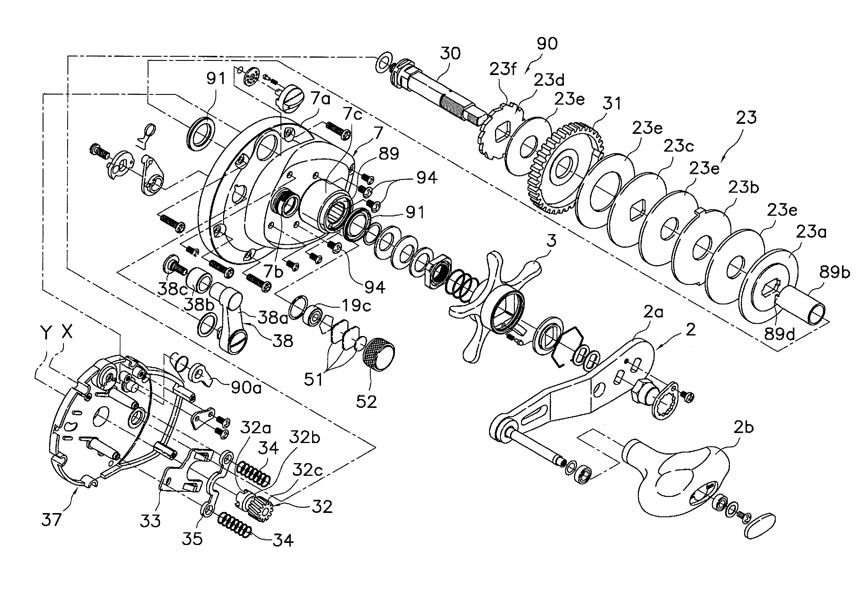
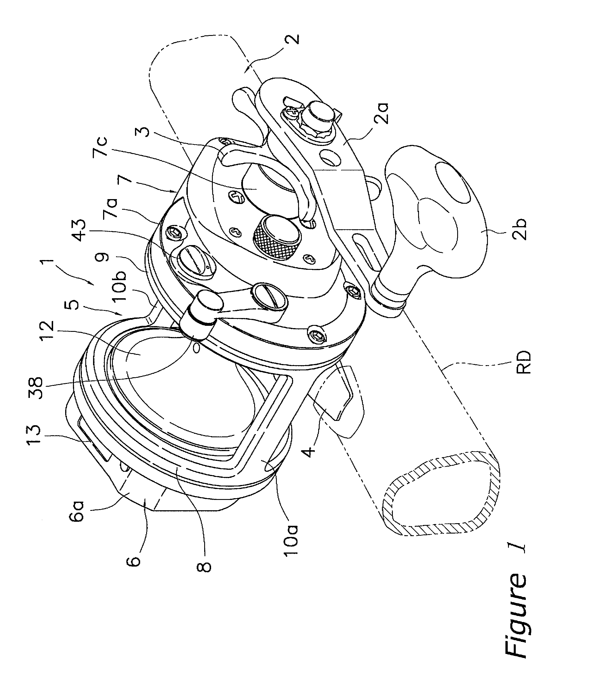
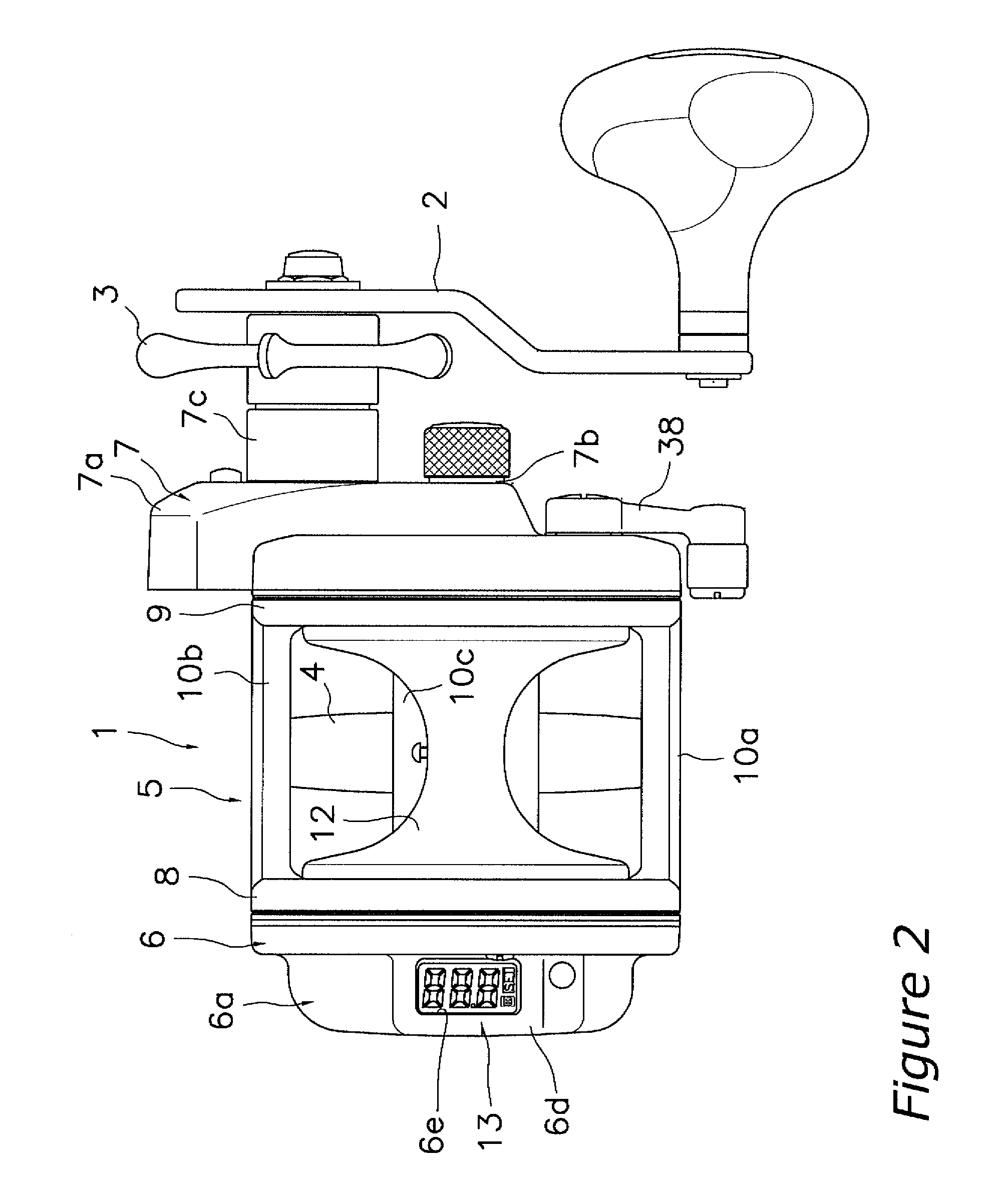
[0032]With reference to FIGS. 1 and 2, a dual bearing reel according to an embodiment of the present invention can be mounted to a fishing rod, and pays out fishing line in the forward direction. For example, the dual bearing reel is a medium sized round type of reel that can wind fishing line of No. 18 about 150 m. The dual bearing reel includes a reel unit 1, a fishing line winding operation handle 2 that is disposed on the side of the reel unit 1, and a star drag 3 that is disposed on the handle 2 on the reel unit 1 side.

[0033]Note that the front / rear side and the left / right side in the following description are defined as the front side is a direction in that the fishing line is paid out in the state where the dual bearing reel is mounted to the fishing rod, and as the left / right side is defined when the dual bearing reel is viewed from the rear side.

[0034]Also, as shown in FIGS. 3 to 5, the dual bearing reel includes a line winding spool 12, a water depth indicator 13, a spool ...


PUM


Abstract

A handle shaft support structure rotatably supports a handle shaft on a reel unit, and includes a boss portion, a roller type one-way clutch, and a pair of seal members. The boss portion is a cylindrical member that is detachably mounted to the reel unit. The one-way clutch includes an outer ring that is non-rotatably coupled to the inner peripheral surface of the boss portion, an inner ring that is arranged on the outer periphery of the handle shaft and is integrally rotatably coupled to the handle shaft, and rolling elements that are arranged between the outer and inner rings. The one-way clutch supports the handle shaft rotatably only in one direction. The pair of seal members are members that are arranged on the both sides of the one-way clutch to seal the one-way clutch.

Description

CROSS-REFERENCE TO RELATED APPLICATIONS[0001]This application claims priority under 35 U.S.C. § 119 to Japanese Patent Application No. 2007-013089, filed in Japan on Jan. 23, 2007, the entire contents of which are hereby incorporated herein by reference.BACKGROUND OF THE INVENTION[0002]1. Field of the Invention[0003]The present invention relates to a dual bearing reel handle shaft support structure, and in particular to a dual bearing reel handle shaft support structure that rotatably supports a handle shaft on a reel unit of a dual bearing reel.[0004]2. Background Information[0005]Generally, a dual bearing reel has a handle shaft with a handle non-rotatably coupled thereto. In order to activate the drag mechanism of the dual bearing reel, this type of handle shaft is prohibited from rotating in the line reel-out direction by a one-way clutch. The type of one-way clutch employed is a roller type one-way clutch, which is capable of supporting the rotation of a the handle shaft and ca...

Claims


Application Information

Patent Timeline
Patent Type & Authority Applications(United States)
IPC IPC(8): A01K89/00
CPCA01K89/015A01K89/01903A01K89/01928A01K89/0155
Inventor TAKECHI, KUNIOKAWASAKI, KEN'ICHI
Owner SHIMANO INC
Why Eureka
Try Eureka