
Method and device for imaging test objects by means of millimeter waves, in particular for inspecting individuals for suspicious objects

Active Publication Date: 2008-07-24
SMITHS HEIMANN
View PDF13 Cites 38 Cited by
  • Summary
  • Abstract
  • Description
  • Claims
  • Application Information

AI Technical Summary

Benefits of technology

[0007]It is therefore an object of the present invention to provide a method for imaging test objects by means of millimeter waves that requires a less complicated apparatus to carry it out and that can thus be implemented in a more economical manner.
[0010]As a result of the circumferential motion perpendicular to the longitudinal axis of the test object, every point on the surface of the object is sensed from multiple perspectives. The common analysis of these perspectives based on the SAR (synthetic aperture) principle corresponds to an antenna that is effectively much larger, resulting in an improvement in resolution perpendicular to the longitudinal axis of the object. The pulse radar or FMCW (frequency modulated continuous wave) radar principle is used for analysis in the direction of the longitudinal axis of the test object. Thus, the reflected signal corresponding to every radiated signal can be identified, and the surface structure can be reconstructed from the determination of the propagation time. Illumination diagonally from above and / or below achieves the greatest propagation time differences for adjacent points on the surface of the test object, thus improving resolution in the direction of the longitudinal axis.

Problems solved by technology

Metal detectors have the disadvantage that they cannot detect any dangerous nonmetallic objects such as plastic weapons or explosives.
Manual scanning is time-consuming and under certain circumstances is experienced as an invasion of privacy.
The prior art devices for carrying out these methods require a complicated structure and are thus very expensive.

Method used


Image

  • Method and device for imaging test objects by means of millimeter waves, in particular for inspecting individuals for suspicious objects
  • Method and device for imaging test objects by means of millimeter waves, in particular for inspecting individuals for suspicious objects

Examples


Embodiment Construction

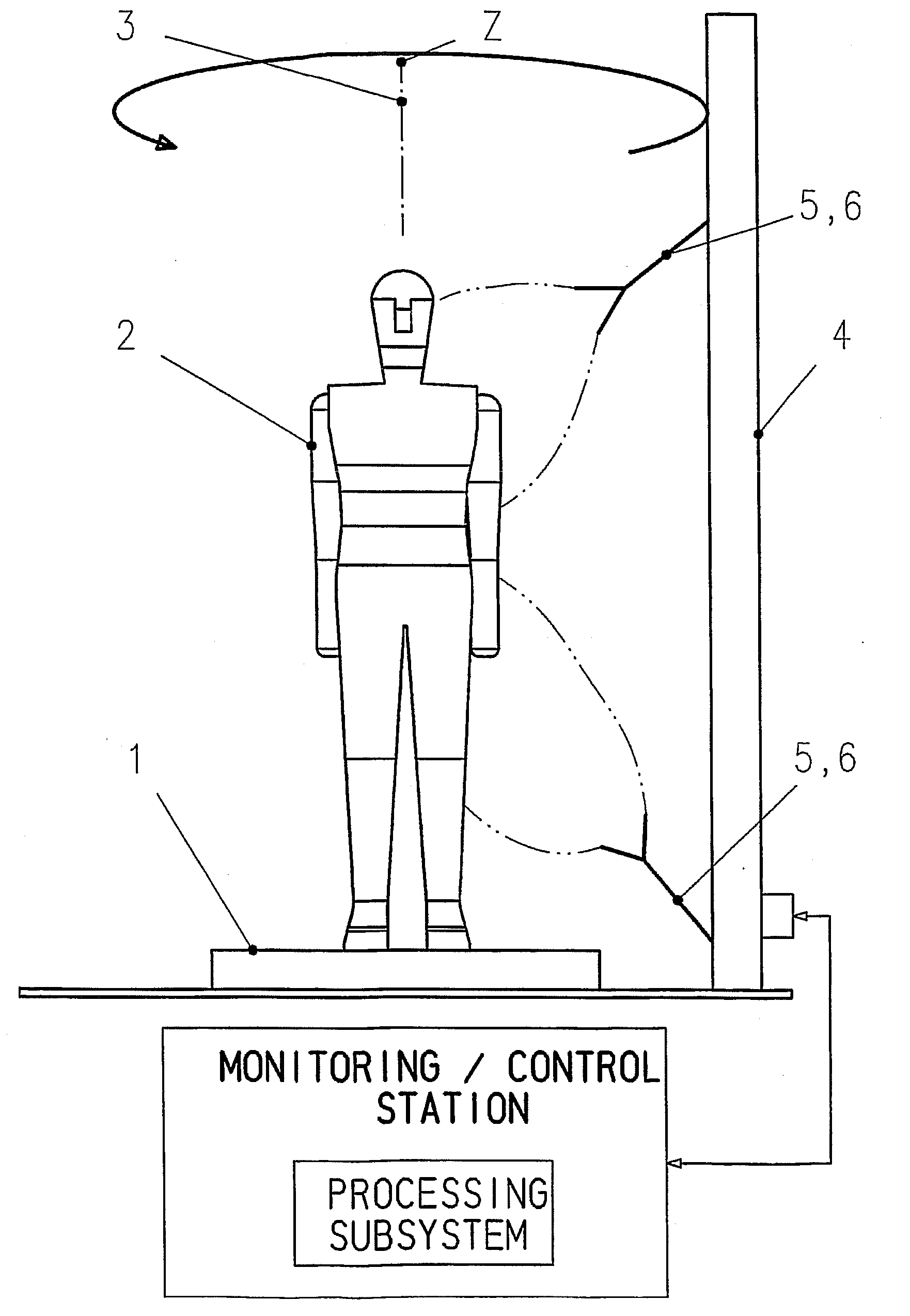
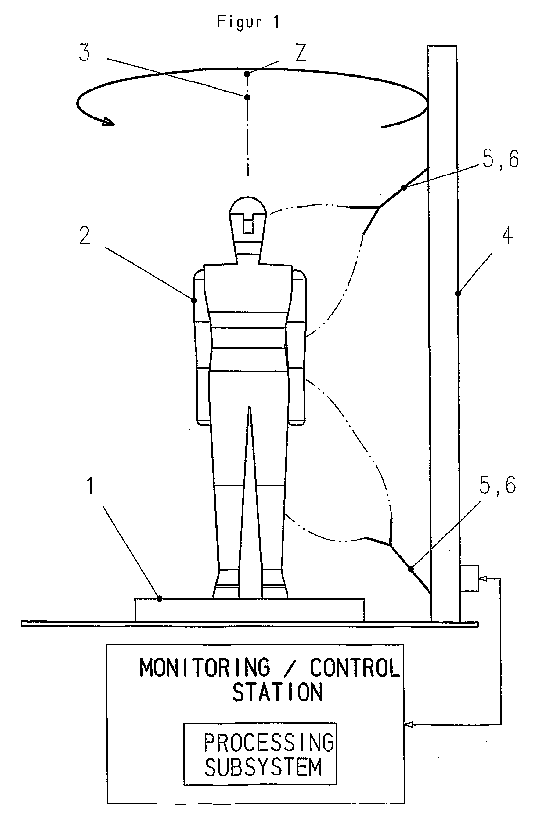
[0015]The device shown in FIG. 1 is used for inspecting airline passengers for suspicious substances such as weapons or explosives during check-in at an airport.

[0016]The device includes a platform 1, upon which a passenger 2 stands while the inspection is being carried out. The passenger 2 thus represents the test object. His longitudinal axis 3 extends in the vertical direction during the monitoring.

[0017]In addition, the device includes a frame 4, which is arranged a distance away from the platform 1 and can be pivoted in a circle about the longitudinal axis 3 at a distance from the platform 1 and thus along the circumference of the passenger 2. Fastened into the frame 4 is at least one transmitting and receiving system 5, 6 each having one transmitting antenna and at least one receiving antenna, each of which has a direction of view and reception that is inclined at an angle of 15° to 70°, preferably 20° to 35°, to the longitudinal axis 3 of the test object (passenger 2). Prefer...


PUM


Abstract

A method for imaging test objects by millimeter waves, especially for checking individuals for suspicious objects is provided, whereby the test object is gradually irradiated with millimeter waves along its circumference and the scattered waves are received and evaluated in order to display an image of the test object. A viewing direction of the transmitting area and a direction of reception of the receiving area extend at an angle of 15° to 70°, preferably 20° to 35° to the longitudinal axis of the test object. For evaluation of the scattered waves in the direction of the longitudinal axis of the test object, a pulse radar or FMCW radar technology is used, and for evaluation at an angle to the longitudinal axis, SAR technology is used.

Description

[0001]This nonprovisional application is a continuation of International Application No. PCT / EP2006 / 003169, which was filed on Apr. 7, 2006, and which claims priority to German Patent Application No. DE 102005016106, which was filed in Germany on Apr. 8, 2005, and which are both herein incorporated by reference.BACKGROUND OF THE INVENTION[0002]1. Field of the Invention[0003]The present invention relates to a method for imaging test objects by millimeter waves, in particular for inspecting individuals for suspicious objects, in which the test object is illuminated successively with millimeter waves along its circumference, and the scattered waves are received and analyzed to display an image of the test object. In addition, the invention concerns a device for carrying out the inventive method.[0004]2. Description of the Background Art[0005]In order to inspect individuals such as airline passengers for suspicious objects, such as weapons or explosives, metal detectors are used or the ...

Claims


Application Information

Patent Timeline
IPC IPC(8): G01S13/90
CPCG01S13/87G01S13/887G01V8/005G01S2013/9088G01S13/89G01S13/9088
Inventor DETLEFSEN, JUERGENJECK, MICHAEL
Owner SMITHS HEIMANN
Learn More