

Touch pad device
a technology of touch pad and device, which is applied in the field of touch pad devices, can solve problems such as inconvenient use or operation errors, and achieve the effect of enhancing the applicability of the touch pad devi
- Summary
- Abstract
- Description
- Claims
- Application Information
AI Technical Summary
Benefits of technology
Problems solved by technology
Method used
Image

Examples
Embodiment Construction
[0021]The invention disclosed herein is directed to a touch pad device. In the following description, numerous details are set forth in order to provide a thorough understanding of the present invention. It will be appreciated by one skilled in the art that variations of these specific details are possible while still achieving the results of the present invention. In addition, well-known components are not described in detail in order not to unnecessarily obscure the present invention.
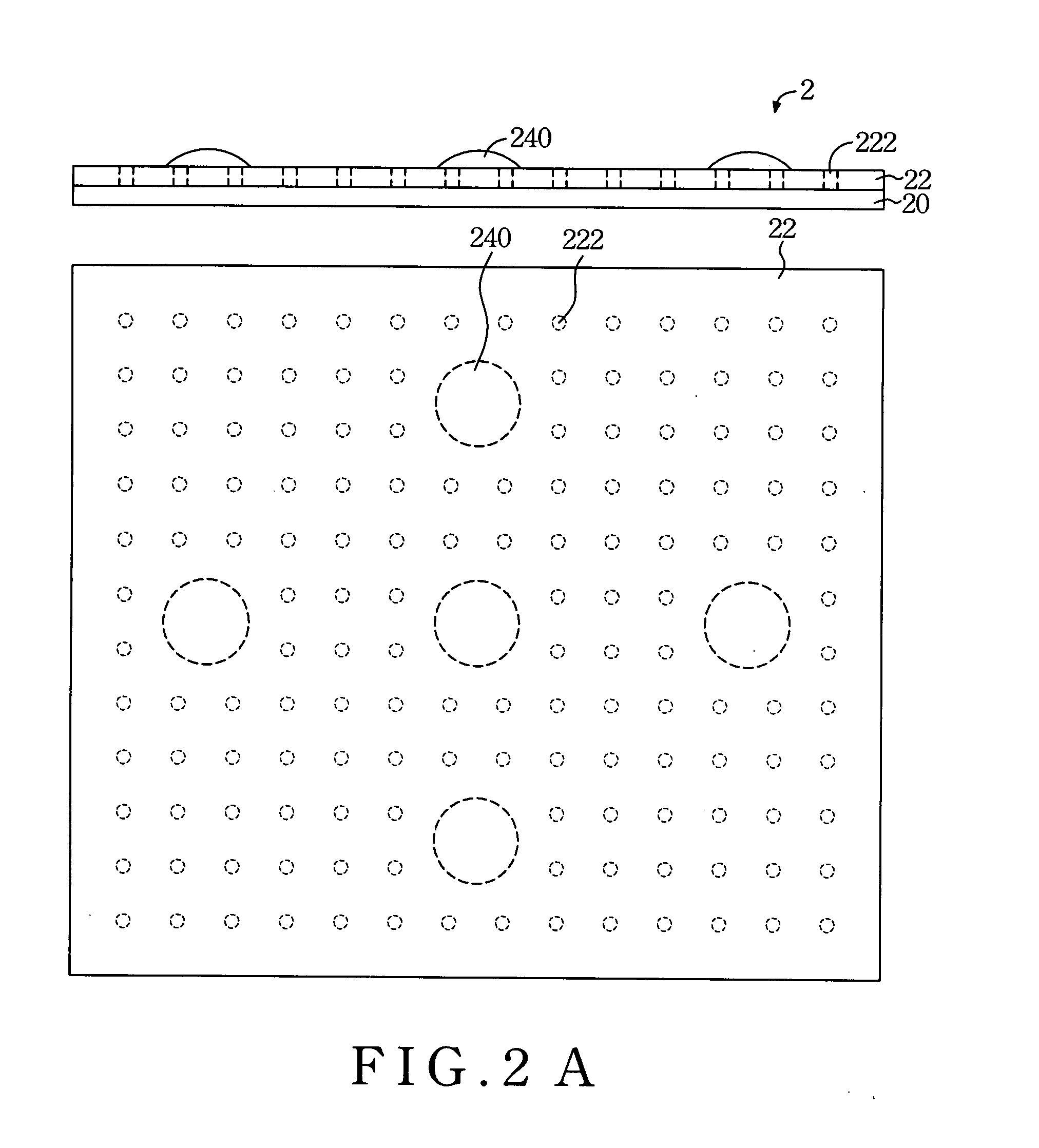
[0022]Referring now to both FIG. 2A and FIG. 2B, a preferred touch pad device of the present invention and a flexible printed circuit board (FPCB) 22 of the touch pad device are shown, respectively.
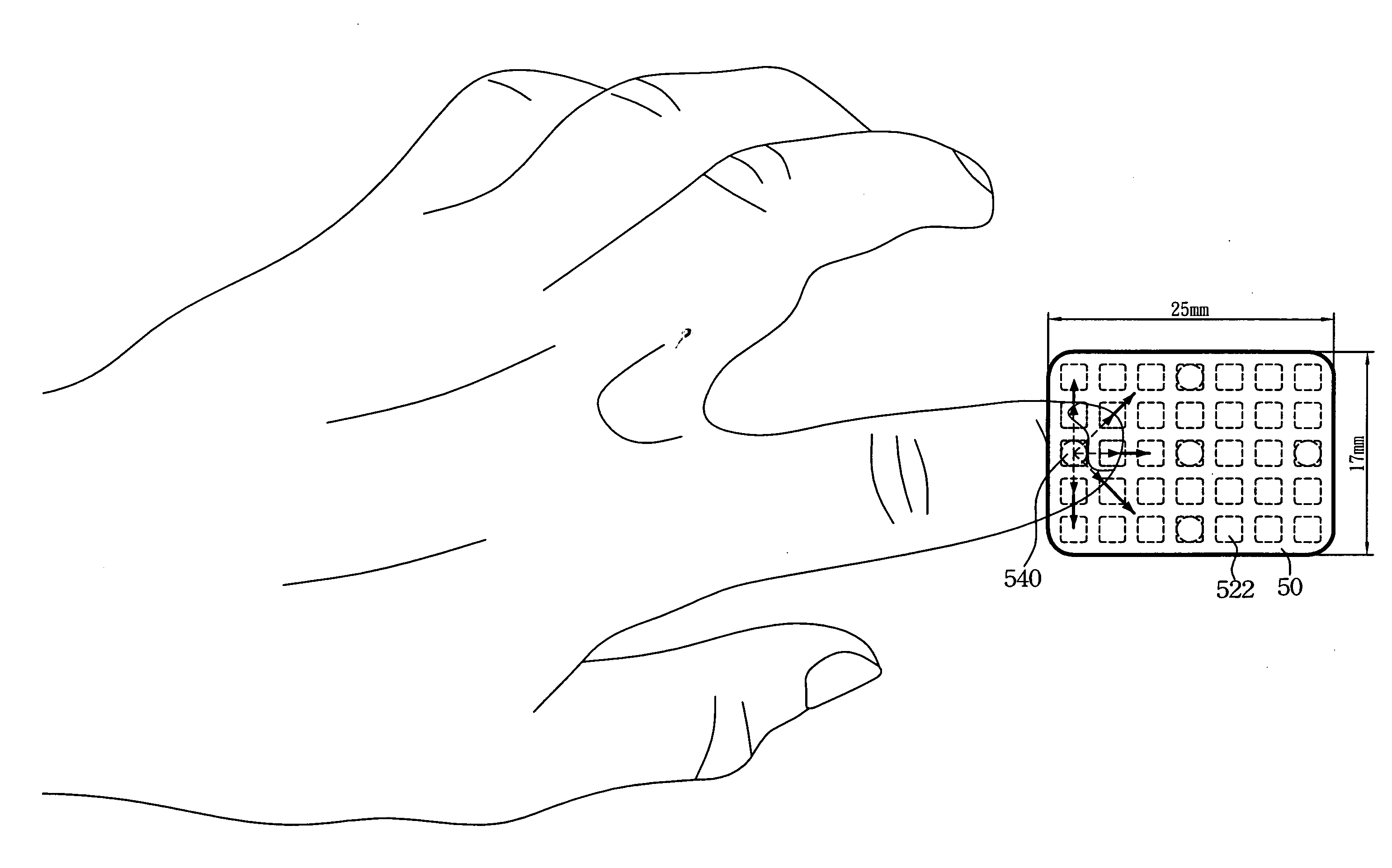
[0023]The touch pad device is mounted inside an electronic apparatus that can be a mobile phone, a personal digital assistant, an MP3 player, an input device of a notebook computer, or any the like. As shown, the touch pad device includes a touch module 2 and a plurality of metal domes 240. In the present i...
PUM
 Abstract
Description
Claims
Application Information