Electronic device and fire protecting mechanism of the electronic device
a technology of electronic devices and fire protection mechanisms, which is applied in the direction of ventilation systems, electrical apparatus casings/cabinets/drawers, instruments, etc., can solve the problems of high cost of foaming coating materials, difficulty in extinguishing fires, and obstruction of self-extinguishing functions
- Summary
- Abstract
- Description
- Claims
- Application Information
AI Technical Summary
Benefits of technology
Problems solved by technology
Method used
Image

Examples
first embodiment
1. First Embodiment of the Present Invention
[0057]First, a structure of an electronic device of a first embodiment of the present invention is discussed and then operations of the electronic device are discussed.
[Structure of Electronic Device]
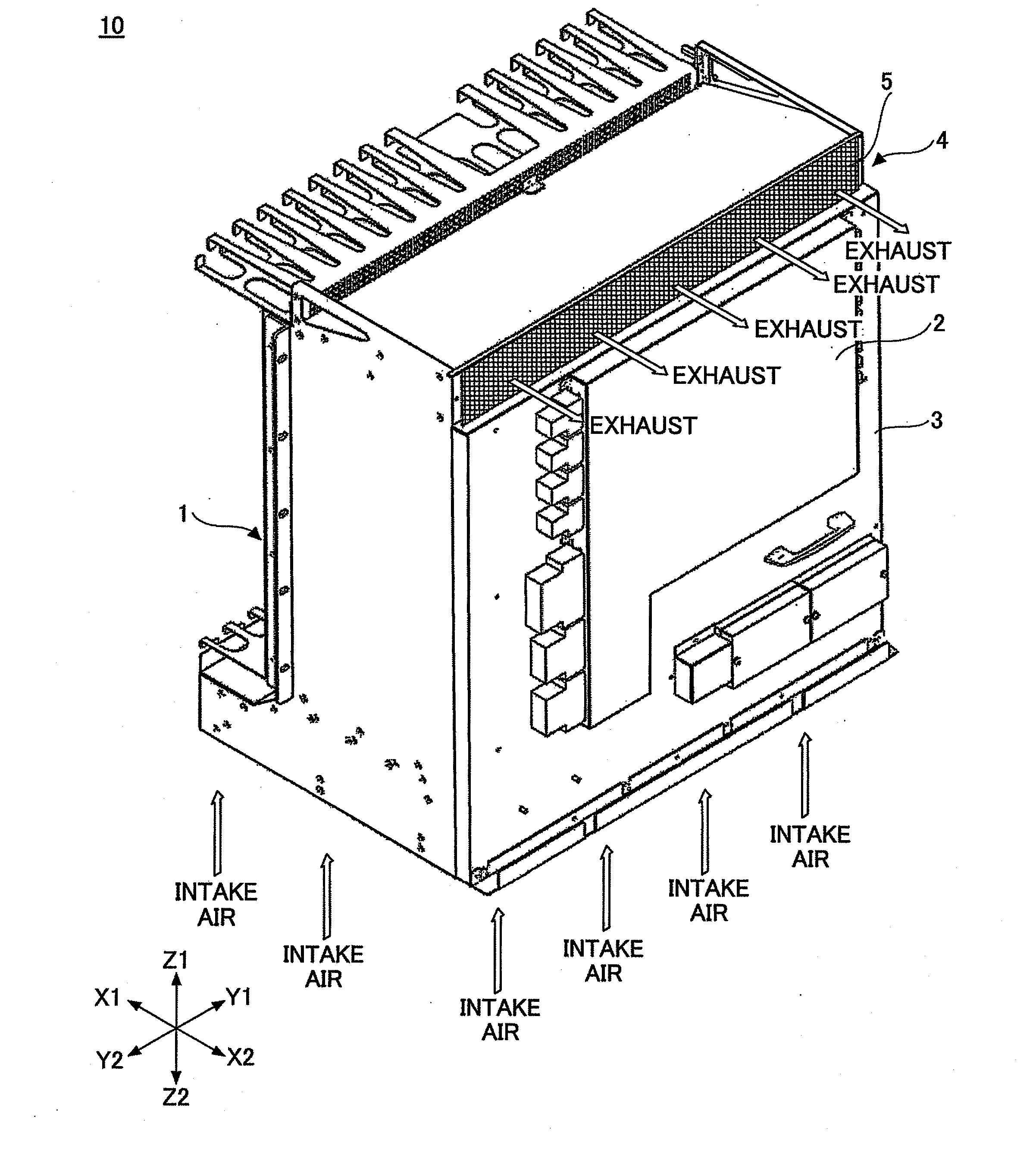
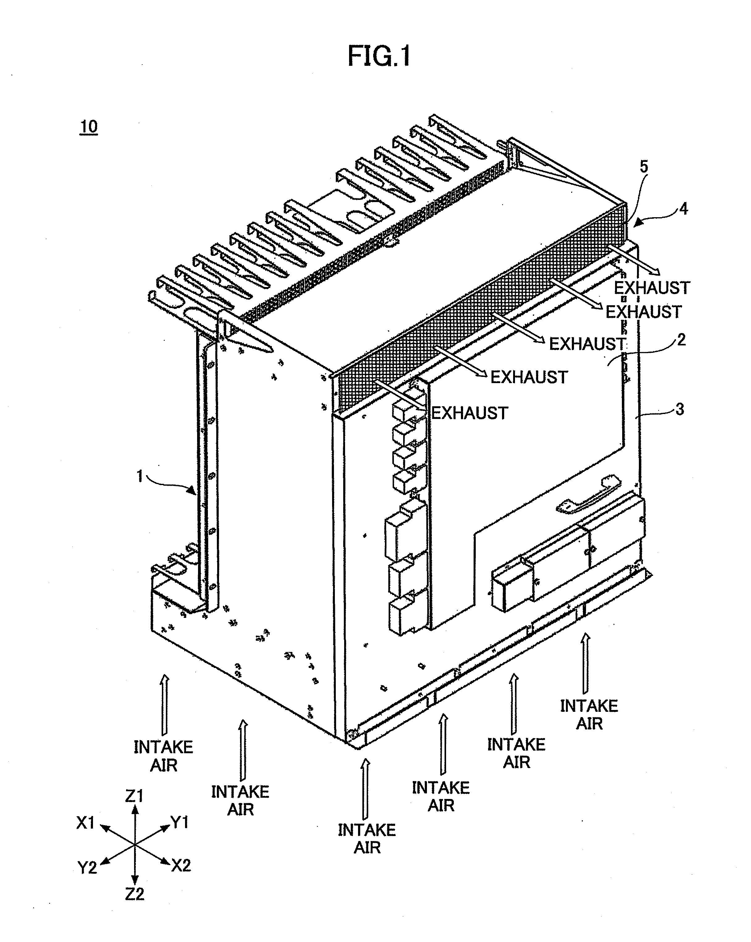
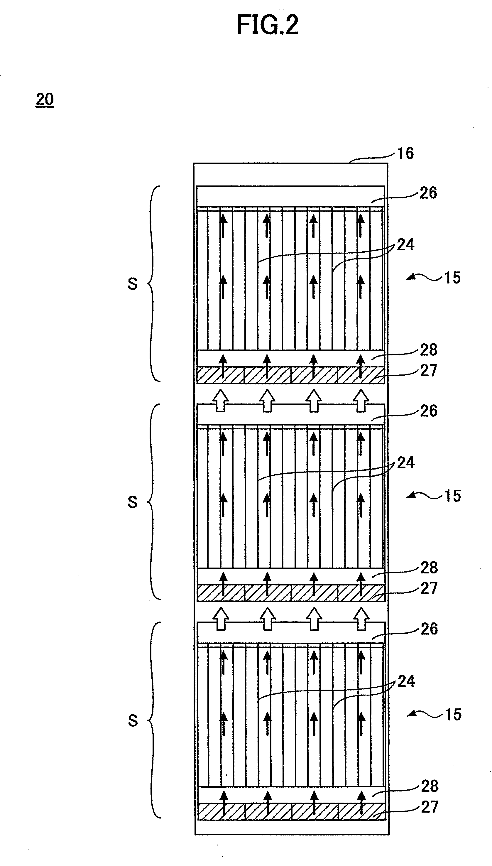
[0058]FIG. 2 is a front view of an electronic apparatus where three steps of electronic devices of a first embodiment of the present invention are provided. FIG. 3 is a rear perspective view seen from a bottom side of the electronic device of the first embodiment of the present invention.
[0059]Referring to FIG. 2, in an electronic apparatus 20, plural (three in the example shown in FIG. 2) electronic devices 15 of the first embodiment of the present invention are stacked in three steps in a cabinet 16. Plural PIUs (plug in unit) where electronic components are mounted on a printed wiring board are received in a shelf S. By a Plug-In method using connectors of the PIUs, the PIUs are connected to a back board provided in the shelf S so that a si...
second embodiment
2. Second Embodiment of the Present Invention
[0148]Next, a second embodiment of the present invention is discussed. Closing structure and mechanisms of door parts at an exhaust opening of an electronic device of the second embodiment of the present invention are different from those of the electronic device 15 of the first embodiment of the present invention. Other parts of the electronic device of the second embodiment are the same as those of the electronic device 15 of the first embodiment of the present invention.
[0149]Accordingly, in the following explanation, the closing structure of the door parts at the exhaust opening of the electronic device of the second embodiment of the present invention is mainly discussed and then operation of the electronic device is discussed. In FIG. 17 through FIG. 32, parts that are the same as the parts shown in FIG. 3 through FIG. 16 are given the same reference numerals, and explanation thereof is omitted.
[Structure of the Electronic Device]
[0...
PUM
 Abstract
Description
Claims
Application Information
 - R&D
- Intellectual Property
- Life Sciences
- Materials
- Tech Scout
- Unparalleled Data Quality
- Higher Quality Content
- 60% Fewer Hallucinations
Browse by: Latest US Patents, China's latest patents, Technical Efficacy Thesaurus, Application Domain, Technology Topic, Popular Technical Reports.
© 2025 PatSnap. All rights reserved.Legal|Privacy policy|Modern Slavery Act Transparency Statement|Sitemap|About US| Contact US: help@patsnap.com