Connecting profile for connecting sheet piles to carrier elements and combined sheet pile wall comprising such a connecting profile

a technology of connecting profile and carrier element, which is applied in the direction of artificial islands, excavations, constructions, etc., can solve the problems of expensive production and achieve the effect of convenient interlocking of sheet piles and simple design

Inactive Publication Date: 2008-07-24
SHEET PILE LLC
View PDF2 Cites 21 Cited by
  • Summary
  • Abstract
  • Description
  • Claims
  • Application Information

AI Technical Summary

Benefits of technology

[0011]In the case of the connecting profile according to the invention, the interaction of the supporting strip with the right-angled hook strip of the interlock profile allows the hooked sheet pile interlock to be held securely in the inner chamber of the interlock. Furthermore, the right-angled shape of the interlock profile of the connecting profile according to the invention can facilitate different shapes of sheet pile interlocks—for example, a LARSSEN interlock, a HOESCH claw or a HOESCH knob—to be brought easily into engagement with a hook section. In so doing, the supporting strip, which is spaced apart from the hook strip, engages with the respective sheet pile interlock with the hook strip in such a manner that at least one so-called three point contact (that is, the sheet pile interlock in the interlock profile is supported at three points as viewed in the cross section of the connecting profile) or, if desired, even a wide area support of the sheet pile interlock in the interlock profile, remains unaffected, thus actively preventing the sheet pile interlock, which is engaged with the hook strip, from detaching.
[0012]The design according to the invention of the interlock profile of the connecting profile permits the connecting profile to be produced by means of a comparatively easy production method, such as hot rolling. If the connecting profile is produced by extrusion, the mold that is to be used for the extrusion is much simpler in design than the molds used for the production of conventional connecting profiles.

Problems solved by technology

The interlock profile is usually adapted to the specific shape of the sheet pile interlock, thus rendering it expensive to produce.

Method used


Image

  • Connecting profile for connecting sheet piles to carrier elements and combined sheet pile wall comprising such a connecting profile
  • Connecting profile for connecting sheet piles to carrier elements and combined sheet pile wall comprising such a connecting profile
  • Connecting profile for connecting sheet piles to carrier elements and combined sheet pile wall comprising such a connecting profile

Examples


first embodiment

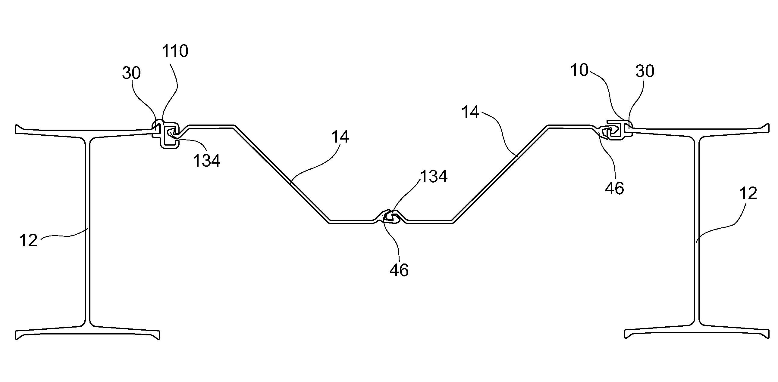
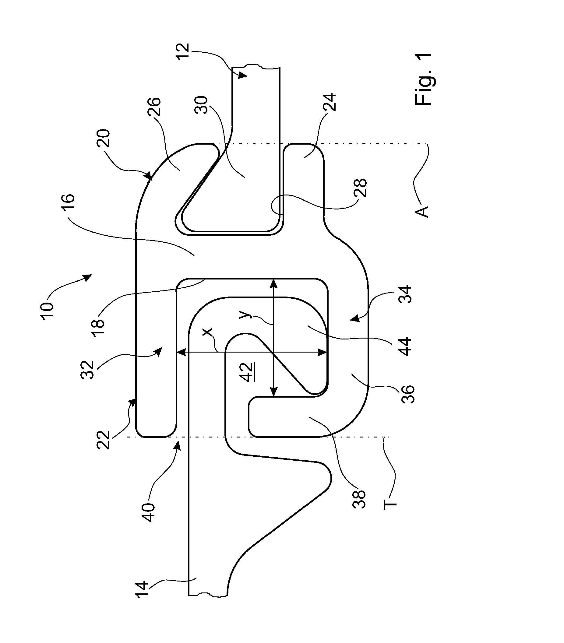
[0033]FIG. 1 depicts a connecting profile 10 configured according to the invention and which is produced by hot rolling and serves to connect a carrier element 12 to a sheet pile 14. The connecting profile 10 exhibits a central center strip 16 having a straight, planar center section 18. The coupling profile 20 for connecting to the carrier element 12 is formed on the flat side which belongs to the center section 18. An interlock profile 22 for coupling an interlock of the sheet pile 14 is formed on the second flat side of the center section 18 that faces away.

[0034]The coupling profile 20 is defined by the center strip 16 off of which a first straight jaw 24 projects at a 90 degree angle in the vicinity of the longitudinal edge, which belongs to the center strip 16 and which is shown at the bottom in FIG. 1 and by a second jaw 26, which projects from the longitudinal edge (shown at the top) of the center strip 16 and is bent in the direction of the first straight jaw 24. The two ja...

second embodiment

[0044]FIG. 4 depicts a connecting profile 70 according to the invention. In the case of this connecting profile 70 the construction of the interlock profile 72 matches that of the interlock 22. The inside cross section of the coupling profile 74 also matches the inside cross section of the coupling profile 20. However, the two jaws 76 and 78 are configured so as to be the mirror inverse of the jaws 24 and 26 of the coupling profile 20, shown in FIG. 1.

[0045]Thus, the angled off jaw 78 adjacent to the hook strip 80 of the interlock profile 72 is formed on the center strip 82. In this case the center strip 82 extends beyond the hook strip 80 and passes over its longitudinal edge into the angled off jaw 78. In contrast, the straight jaw 76 projects outwardly from the flat side of the center strip 82, so that the coupling profile 74, which is offset outwardly in total by approximately one wall thickness of the hook strip 80, is formed on the center strip 82. As a result, the connecting ...

third embodiment

[0051]FIG. 7 depicts a connecting profile 110 according to the invention. The connecting profile 110 also exhibits a center strip 112. One flat side of the center strip has a coupling profile 114 for connecting to the carrier element 12; and the other flat side of the center strip has an interlock profile 116 for hooking an interlock of the sheet piles 14.

[0052]As in the case of the second embodiment shown in FIG. 4, the coupling profile 114 has a straight jaw 118, which projects at a right angle from the center strip 112, and a second jaw 120, which projects in a bent off manner from the center strip 112, so that an inner chamber, which has a trapezoidal shape as viewed in the cross section and which is intended for accommodating the fastening section 30, which has a wedge-shaped cross section and belongs to the carrier element 12, is formed. In this case, the center strip 112 is drawn upwardly and passes over into the bent off jaw 120.

[0053]With respect to the transition of the ce...


PUM


Abstract

A connecting profile of constant cross section that couples sheet piles to carrier elements. The connecting profile exhibits a center strip, on which a coupling profile, which is to be connected to the carrier element, and an interlock profile for hooking an interlock of the sheet pile are formed. The interlock profile exhibits a supporting strip projecting from the center strip and a hook strip projecting from the center strip. The supporting strip projects at least approximately at a right angle from the center strip. The hook strip exhibits a transition section projecting at least approximately at a right angle from the center strip, and a hook section, which runs at least approximately at a right angle to the transition section in the direction of the supporting strip and which defines with the supporting strip a jaw for inserting the interlock of the sheet pile.

Description

CROSS-REFERENCE[0001]This application is a continuation patent application of International Application No. PCT / EP2006 / 006827 filed 12 Jul. 2006, now abandoned. Said application is expressly incorporated herein by reference in its entirety.FIELD[0002]The invention relates to a connecting profile for connecting sheet piles to carrier elements. Furthermore, the invention relates to a combined sheet pile wall comprising such a connecting profile.BACKGROUND[0003]A connecting profile is used, in particular, to build a so-called combined sheet pile wall, where at least one sheet pile is inserted between two carrier elements—for example, double T-shaped carriers, T-shaped carriers, piles and the like. The sheet pile is joined to the carrier elements with the aid of the above-described connecting profiles. Therefore, one of the above-described connecting profiles is arranged between a carrier element and at least one sheet pile.[0004]In order to connect the connecting profile to the carrier...

Claims


Application Information

Patent Timeline
Patent Type & Authority Applications(United States)
IPC IPC(8): E02D5/03
CPCE02D5/08
Inventor HEINDL, RICHARD
Owner SHEET PILE LLC
Why Eureka
Try Eureka