Milling cutter and milling insert with coolant delivery

Active Publication Date: 2008-07-24
KENNAMETAL INC
View PDF99 Cites 91 Cited by
  • Summary
  • Abstract
  • Description
  • Claims
  • Application Information

AI Technical Summary

Problems solved by technology

It is well-known that excessive heat at the insert-chip interface can negatively impact upon (i.e., reduce or shorten) the useful tool life of the milling insert.
As can be appreciated, a shorter useful tool life increases operating costs and decreases overall production efficiency.
A decrease in plastic deformation resistance increases the risk for breakage of the cutting insert.
U.S. Pat. No. 5,775,854 to Wertheim points out that a rise in the working temperature leads to a decrease in hardness of the cutting insert with a consequent increase in wear of the c

Method used


Image

  • Milling cutter and milling insert with coolant delivery
  • Milling cutter and milling insert with coolant delivery
  • Milling cutter and milling insert with coolant delivery

Examples


Embodiment Construction

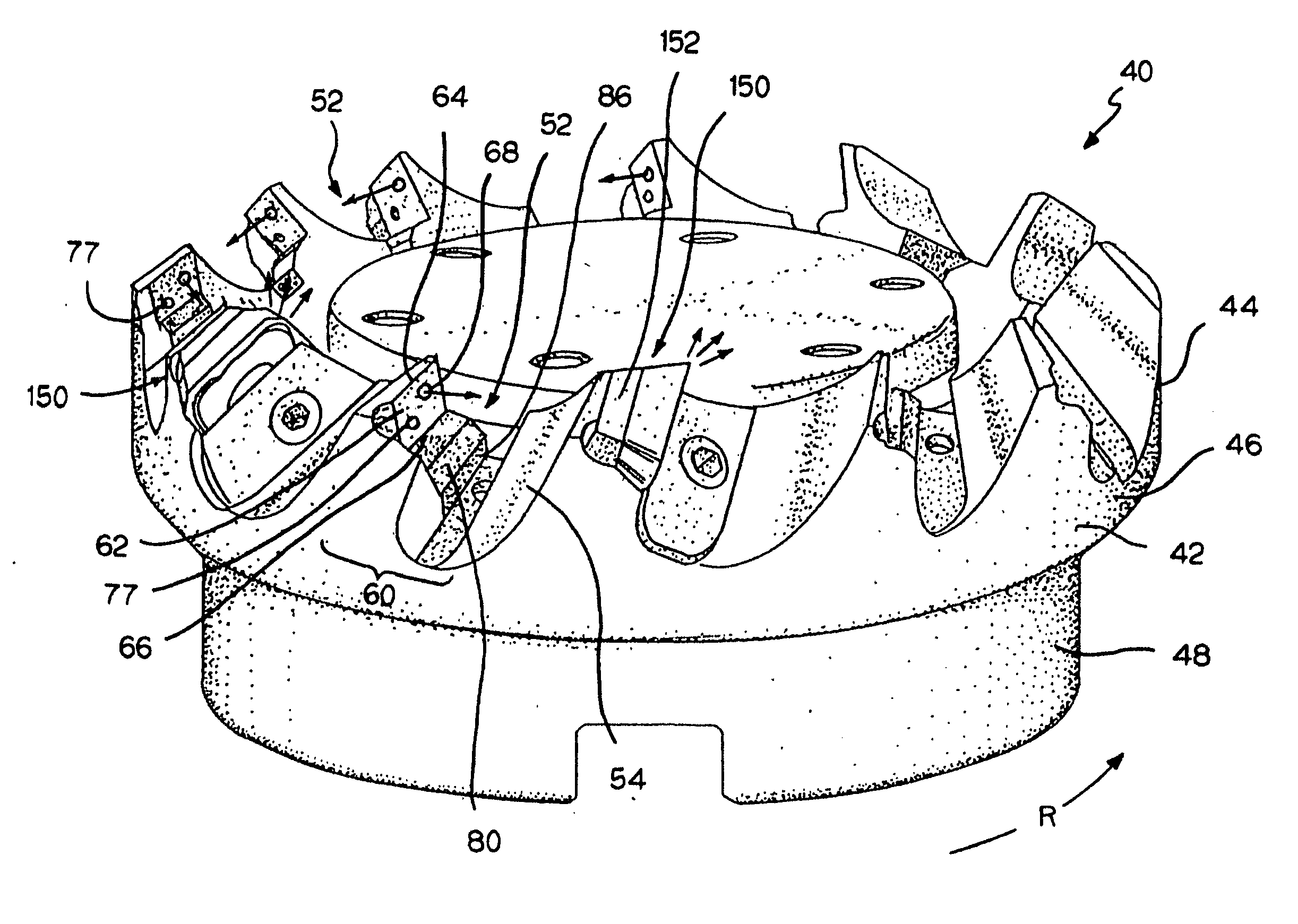
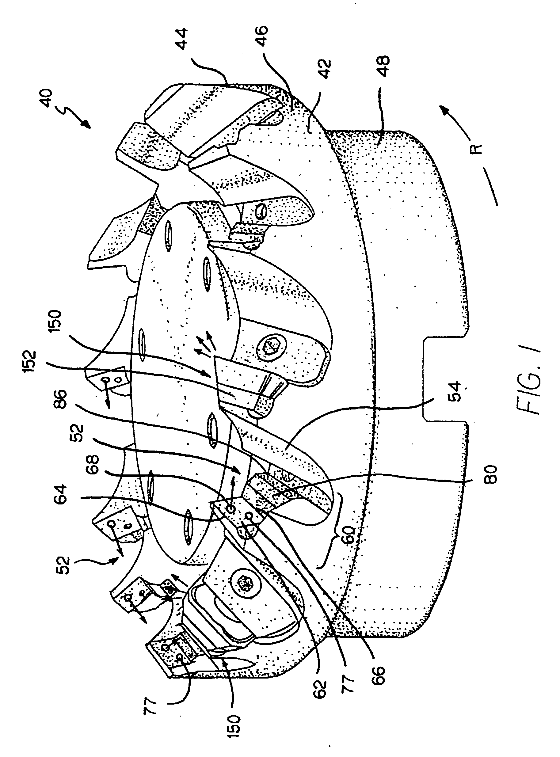
[0043]Referring to the drawings, FIG. 1 illustrates a specific embodiment of the milling cutter assembly of the invention generally designated as 40 wherein the milling cutter assembly 40 is for use in chipforming and material removal operations. In such an operation, the material is removed from a workpiece. In operation, the milling cutter assembly 40 rotates in the direction indicated by the arrow “R”.

[0044]Milling cutter assembly 40 includes a generally cylindrical milling cutter body generally designated as 42 that has a cutting rim 44 with a peripheral surface 46. Milling cutter 40 further includes a depending integral collar 48 that depends downward (as viewed in FIG. 1) from the cutting rim 44. In this specific embodiment, milling cutter assembly 40 further contains a plurality of spaced-apart pockets generally designated as 52 in the peripheral surface 46 of the cutting rim 44. As will be described in more detail hereinafter, each pocket 52 receives and securely retains a m...


PUM

PropertyMeasurementUnit
Volumeaaaaaaaaaa
Shapeaaaaaaaaaa

Abstract

A cutting insert for use in chipforming and material removal from a workpiece wherein coolant is supplied to the cutting insert from a coolant source. The cutting insert includes at least one discrete cutting location and at least one distinct internal channel that corresponds to the cutting location. The internal channel has an inlet to receive coolant and an outlet to exit coolant. The outlet is proximate to the cutting location, and the inlet is radial inward of the outlet.

Description

BACKGROUND OF THE INVENTION[0001]The invention relates to a milling cutter, as well as a milling insert, used for chipforming and material removal operations. More specifically, the invention pertains to a milling cutter, as well as a milling insert, used for chipforming and material removal operations wherein there is enhanced delivery of coolant adjacent the interface between the milling insert and the workpiece (i.e., the insert-chip interface) to diminish excessive heat at the insert-chip interface.[0002]In a chipforming and material removal operation (e.g., a milling operation), heat is generated at the interface between the cutting insert and the location where the chip is removed from the workpiece (i.e., the insert-chip interface). It is well-known that excessive heat at the insert-chip interface can negatively impact upon (i.e., reduce or shorten) the useful tool life of the milling insert. As can be appreciated, a shorter useful tool life increases operating costs and decr...

Claims


Application Information

Patent Timeline
IPC IPC(8): B23P15/28
CPCB23C5/2221B23C5/28B23C2200/085B23C2200/086B23C2210/166B23Q11/10Y10T407/235Y10T408/44Y10T407/11Y10T407/27Y10T407/14Y10T407/1926Y10T407/191Y10T407/23B23C5/2213
Inventor PRICHARD, PAUL D.ANDRAS, LINN R.
Owner KENNAMETAL INC
Why Eureka
Try Eureka