

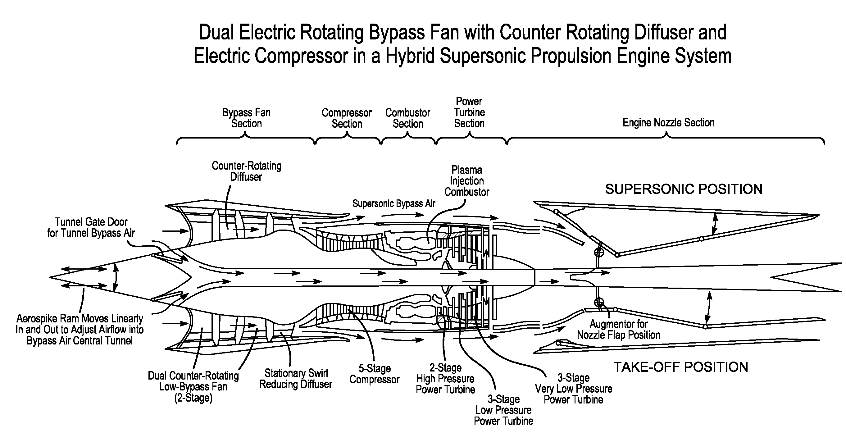
Electric turbine bypass fan and compressor for hybrid propulsion
a technology of bypass fan and compressor, which is applied in the direction of machines/engines, stators, liquid fuel engines, etc., can solve the problems of gas turbine engines, devices powered by gas turbine engines, and limited overall design and performance, so as to reduce the number of rotor/diffuser compressor stages
- Summary
- Abstract
- Description
- Claims
- Application Information
AI Technical Summary
Benefits of technology
Problems solved by technology
Method used
Image

Examples
Embodiment Construction
[0034]For the purposes of promoting an understanding of the principles of the invention, reference will now be made to the embodiments of the present invention illustrated in the drawing figures briefly described above. It will nevertheless be understood that no limitation of the scope of the invention is thereby intended, such alterations and further modifications in the illustrated device, and such further applications of the principles of the invention as illustrated therein being contemplated as would normally occur to one skilled in the art to which the invention relates.
[0035]The key operations of the electric by-pass fan and electric turbocompressor-compounding compressor turbine system are that they are disengaged or engaged electrically, so that combustion cycles, compressor ratios, compressor cooling, thrust, and electric generation can be arranged and optimized for high thermodynamic and combustion efficiencies across the entire flight envelope, regardless of altitude, ai...
PUM
 Abstract
Description
Claims
Application Information