

Chain transmission device
- Summary
- Abstract
- Description
- Claims
- Application Information
AI Technical Summary
Benefits of technology
Problems solved by technology
Method used
Image

Examples
first embodiment
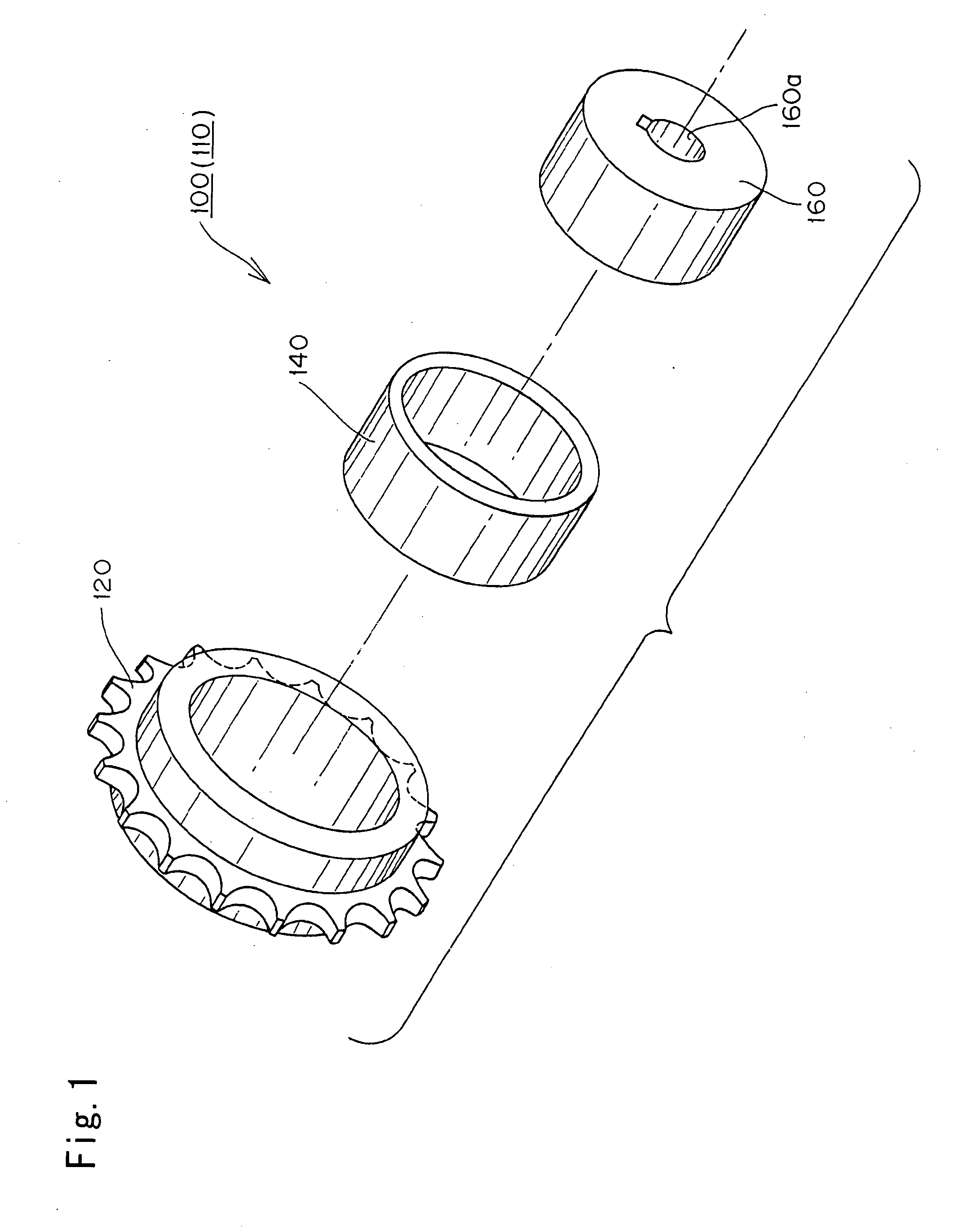
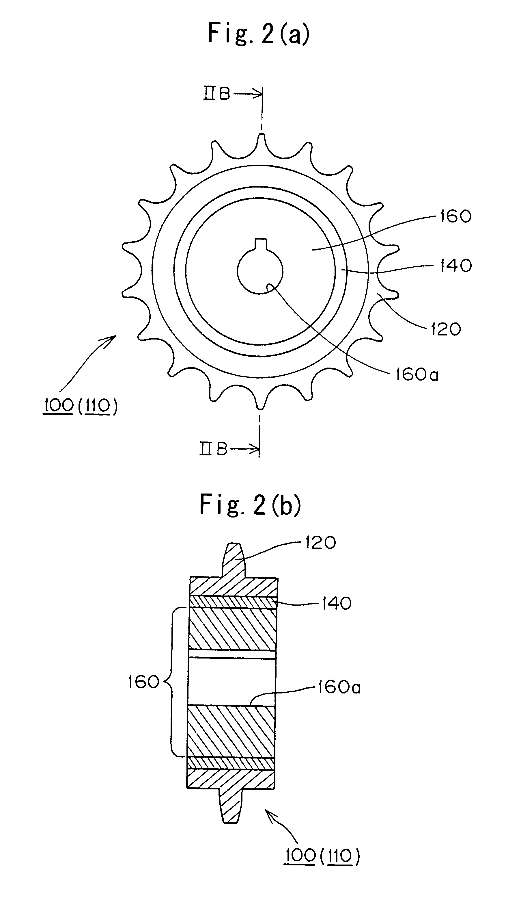
[0047]As shown in FIGS. 1 and 2, in the invention, an elastic member 140 is attached to an inner hub 160 of the sprocket. The hub includes a keyed shaft-receiving hole 160a to which a shaft can be fitted. An outer circumferential member 120, on which the sprocket teeth are formed, surrounds the elastic member 140. The elastic material can be resin, rubber, metal or the like, but the material of the elastic member should have a Young's modulus smaller than that of the outer circumferential member 120.
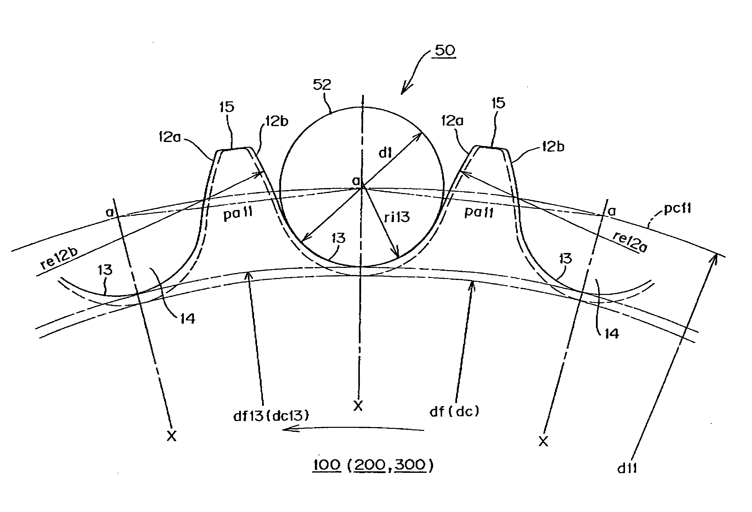
[0048]The sprocket 100 has a tooth form, shown in FIG. 8, which is different from the standard ISO tooth form as shown in FIG. 12 and as represented by the broken line in FIG. 8. Referring to FIG. 8, in the sprocket 100, the sprocket teeth 15 are separated by tooth gaps or grooves 14. The adjacent teeth have facing tooth surface 12a and 12b, which are continuous with a tooth gap bottom 13.
[0049]The tooth surface 12a of the sprocket 100 is a front surface with reference to the direction o...
second embodiment
[0054]A chain transmission according to the invention is shown in FIGS. 3, 4(a) and 4(b), and its sprocket tooth form is as illustrated in FIG. 8. An outer circumferential member 220, on which the sprocket teeth 220a are formed, surrounds an elastic member 240. The elastic material can be resin, rubber, metal or the like, but the material of the elastic member should have a Young's modulus lower than that of the outer circumferential member 220.
[0055]The sprocket has a tooth form as shown in FIG. 8, which is different from the standard ISO tooth form. The root diameter (i.e., the diameter of the tooth gap bottom circle) is greater than the root diameter of the standard ISO tooth form, and, in the case of a sprocket having an odd number of teeth, the caliper diameter is also greater than the caliper diameter of the ISO tooth form. The details of the sprocket 200 are the same as in the first embodiment and are illustrated in FIG. 8.
third embodiment
[0056]In a sprocket according to the invention, as shown in FIGS. 5 and 6, an elastic member 340 is sandwiched between an inner circumferential hub 360 and an outer circumferential member 320 on which sprocket teeth are formed. The hub has a keyed shaft hole 360a to which a shaft can be fitted. The elastic member 340 is composed of a material such as resin, rubber, metal, or the like, having a Young's modulus lower than that of the outer circumferential member 320.
[0057]The elastic member 340 is formed with a plurality of spaced cylindrical portions 340a, disposed at equal intervals around the circumference of the elastic member. The cylindrical members are connected by arc-shaped plates 340b. The elastic member 340 is sandwiched between the outer circumferential surface of the inner circumferential hub 360 and an inner circumferential surface of the toothed outer circumferential member 320. The cylindrical portions 340a are fitted between opposed concave grooves 360b and 320a respe...
PUM
 Abstract
Description
Claims
Application Information