Expansion Rod, Self-Adjusting

a self-adjusting and expansion rod technology, applied in the field of expansion rods, can solve the problems of difficult pictorially representation, especially in cross-sections

Inactive Publication Date: 2008-07-24
SCHWAB HELMUT
View PDF8 Cites 148 Cited by
  • Summary
  • Abstract
  • Description
  • Claims
  • Application Information

AI Technical Summary

Benefits of technology

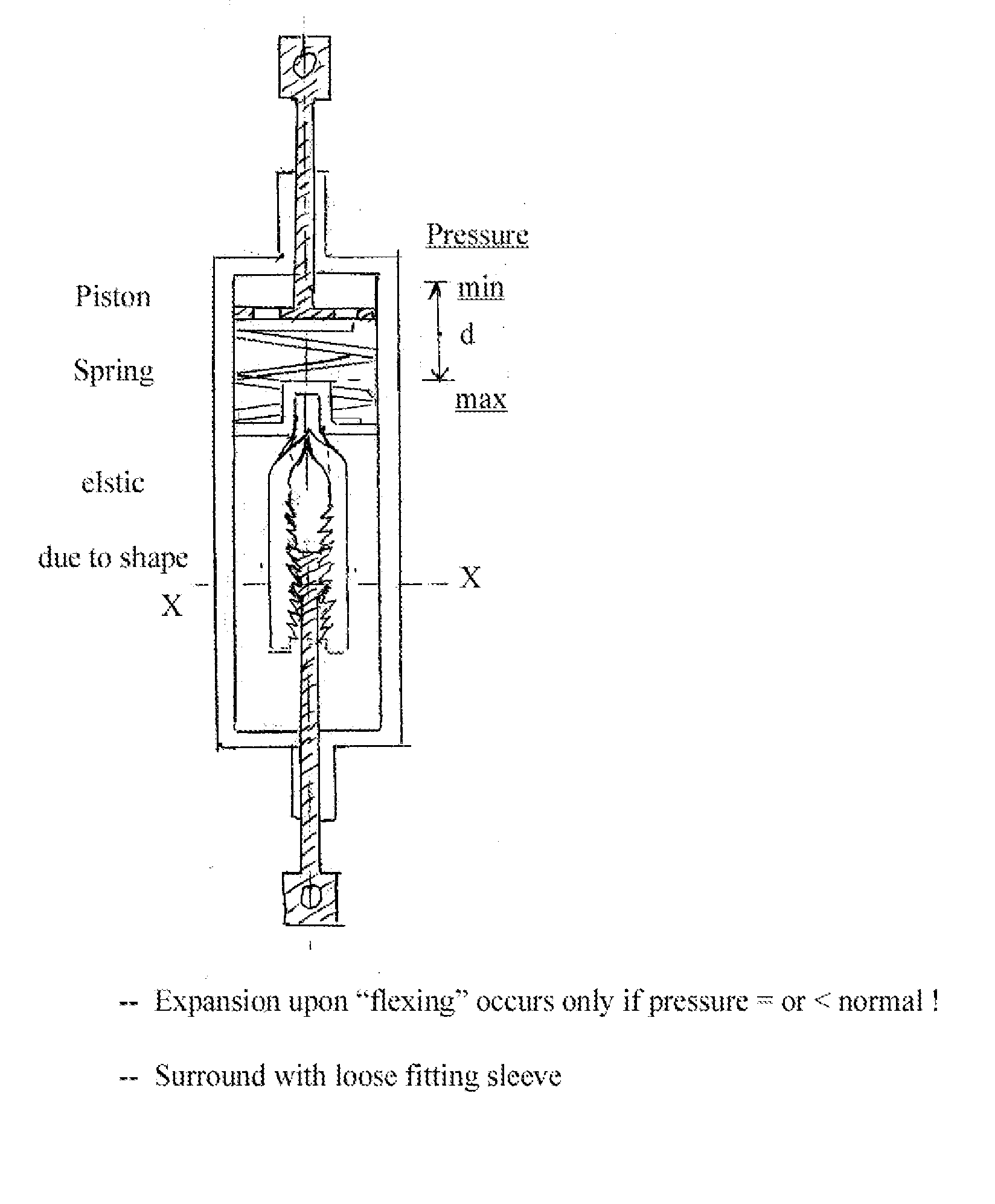
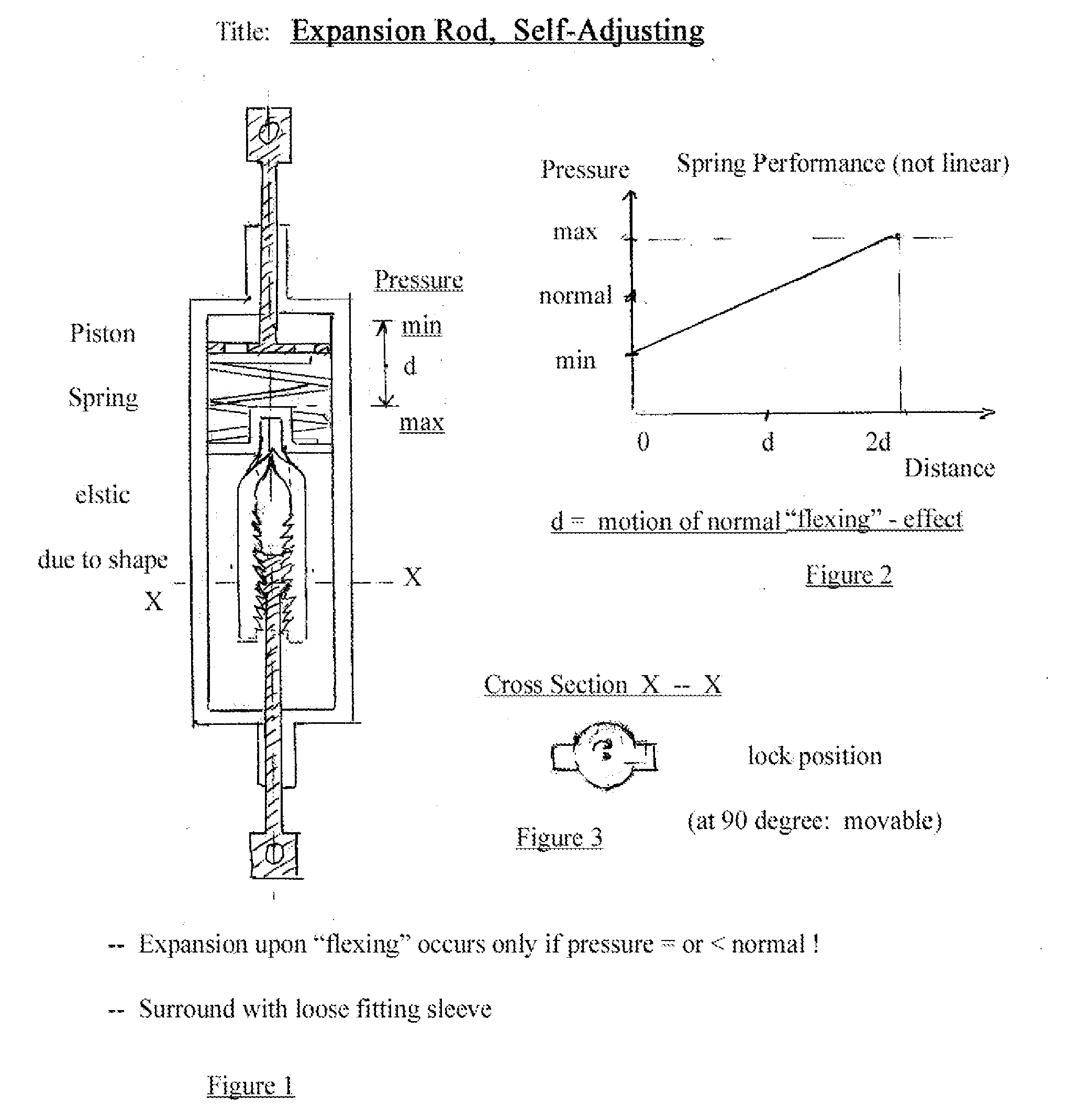
[0017]Rotation of the piston by 90 degrees, as upon or before implantation, liberates the piston from the ratchet engagement and allows the movement of the piston far into the rod—for the

Problems solved by technology

Actual executions would be more slim and elongated for suitability as implan

Method used


Image

  • Expansion Rod, Self-Adjusting
  • Expansion Rod, Self-Adjusting

Examples


Embodiment Construction

of the Functioning of the Invention “Expansion Rod, Self-Adjusting”:

[0022]Upon proper implantation of the “Expansion Rod, Self-Adjusting”, the rod should initially not exert any expansion pressure—in order to facilitate implantation—but should correspond in length to the uncorrected distance between its anchoring points.

[0023]In this case, the piston in the “upper” section will be pushed by the spring to its top position, stopped at this point by the rod chamber.

[0024]When properly installed, the ratchet system in the “lower” section of the “Expansion Rod, Self-Adjusting” will be in its shortest (most “pushed-in) or a very short position by way of adjustment as described before—just long enough to be anchored easily.

[0025]After implantation, upon a demanded flexing movement by the patient as prescribed by the physician, such that the distance in the rod area would increase, the piston will pull against the rod assembly and, thereby, will result in a corresponding movement in the rat...


PUM


Abstract

The design of a rod is disclosed that can serve, among other more general applications, as an implant to stimulate the reduction of spinal deformity. Different from common solid rod implants, the here-disclosed rod provides an almost uniform pressure between a chosen maximum and minimum by means of an internal spring and by expanding its length to adjust for progressing spinal growth or adjustment. The rod contains an internal ratchet which permits a piston to expand only outward, thereby providing easy installation and the expansion of the rod over time as the spine adjusts. The controlled expansion occurs in surgical applications through occasional body flexing, thereby avoiding additional interventions for adjustment.

Description

ABSTRACT / SUMMARY[0001]A rod contains an internal ratchet which permits a piston to expand only outward, thereby providing an expansion of the rod. The expansion occurs, in the case of orthopedic applications, through body flexing. An internal spring and piston restricts the expansion within a pre-selected pressure range.CROSS REFERENCE TO RELATED APPLICATIONS, GENERAL BACKGROUND[0002]Orthopedic deformations, specifically of the spine, call for corrective therapy. It is known that temporarily forced adjustment of form can lead not only to short term forced recovery of form but also to long-term natural and permanent recovery of form. Therefore, it is customary to implant various rods or other mechanical elements and attach those by means of screws or other fasteners to bone elements to provide such forced adjustment of form.[0003]A specific problem arises with the natural adjustment or growth of bone or spine segments. Not only should an optimal amount of pressure of the inserted ele...

Claims


Application Information

Patent Timeline
IPC IPC(8): A61B17/58
CPCA61B17/7014
Inventor SCHWAB, HELMUT
Owner SCHWAB HELMUT
Why Eureka
Try Eureka