Peripheral switching device and a peripheral switching control device

a control device and peripheral technology, applied in the field of peripheral switching devices, can solve the problems of wasting resources, difficult to secure the quality of important services such as telephones, and avoiding conventional techniques

Inactive Publication Date: 2008-07-24
NTT DOCOMO INC
View PDF12 Cites 23 Cited by
  • Summary
  • Abstract
  • Description
  • Claims
  • Application Information

AI Technical Summary

Benefits of technology

[0056]FIG. 13 is a flow chart showing a procedure of controlling input to and output from a peripheral in the peripheral switching device and the switching control device according to the first embodiment of the present invention.
[0057]FIG. 14 is a flow chart showing a peripheral switching locking procedure in a peripheral switching control device according to a modified example 1 of the present invention.
[0058]FIG. 15 is a flow chart showing a peripheral switching locking procedure in the peripheral switching control device according to a modified example 1 of the present invention.

Problems solved by technology

However, the foregoing conventional technique is not provided with means for prohibiting (locking) switching of the ownership of a certain peripheral between Oss and means for flexibly arbitrating peripheral contention between OSs.
For this reason, with the conventional technique, it is difficult to secure quality of important services such as a telephone.
Moreover, the conventional technique has a problem of uselessly consuming resources when a peripheral shared by multiple OSs is set to off by one of the OSs, because the other OS keeps on attempting to communicate with the peripheral without being aware that the peripheral has been set to off.
This useless resource consumption is caused by a lack of controller for stopping the other OS from making communications for input-output with the peripheral.
The conventional technique, however, does not support such a case.
If the OS to which the microphone and the speaker are assigned is switched to background OS under the conditions in which the telephone application is currently used for telephone conversations, a problem occurs that the call through the telephone application is disrupted.
Unless the switching of the OSs between foreground OS and background OS is forcibly performed, the OS having the faulty or anomaly shows a faulty screen on the LCD to the user, and thereby the user may be bewildered.
In addition, if a peripheral is assigned to the OS having the faulty or anomaly, the user unavoidably operates on the OS having the faulty or anomaly.
As a result, inappropriate processing may be performed.
On the other hand, if the ownership of the microphone and the speaker is controlled separately from the aforementioned switch button, a problem of a contention for the peripheral between the OSs has occurred.
When there is an incoming call to the background OS while a speech recognition application owns and uses the microphone on the foreground OS, there is a possibility that it is impossible to execute a telephone call operation in response to the incoming call, because the foreground OS uses the microphone exclusively.
Specifically, when there is an incoming call to the foregoing OS while a speech recognition application owns and uses the microphone on the background OS, it may be also impossible to perform a telephone call operation in response to the incoming call.
Even when the priority of a first OS is set higher or lower than that of a second OS in an environment where the two OSs are installed, the same problem still exists.
In this way, resources may be consumed in vain in some cases.

Method used


Image

  • Peripheral switching device and a peripheral switching control device
  • Peripheral switching device and a peripheral switching control device
  • Peripheral switching device and a peripheral switching control device

Examples


first embodiment

Configuration of Computer System of the Invention

[0059]A configuration of a computer system according to a first embodiment of the present invention will be described by referring FIGS. 1 to 8.

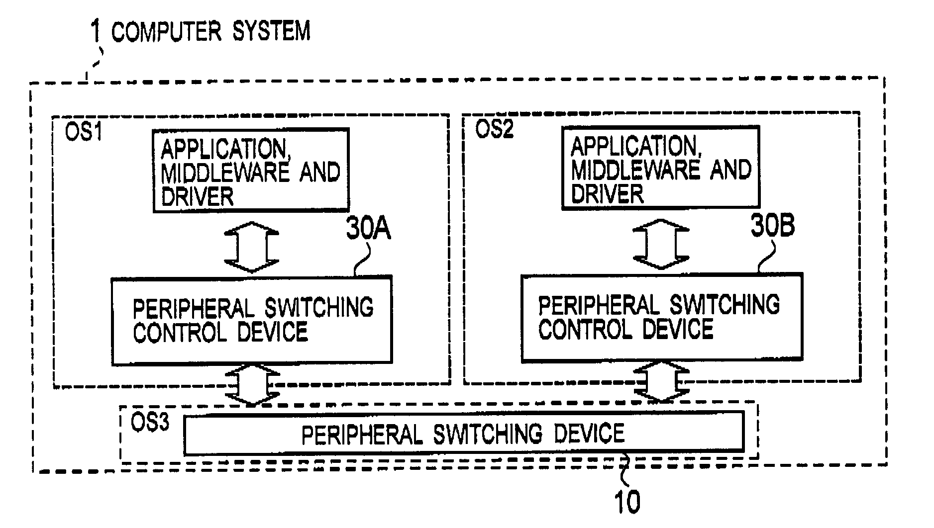
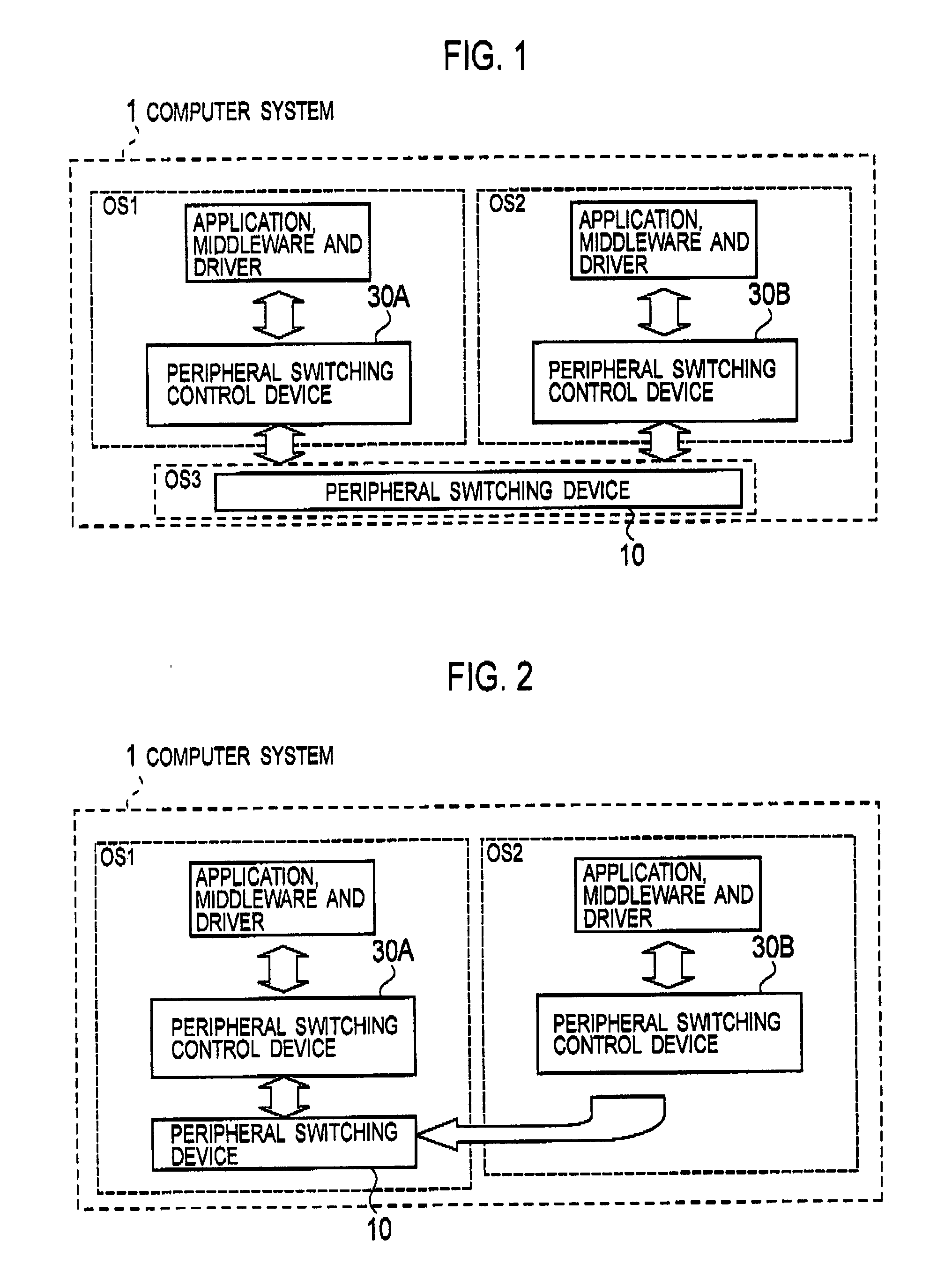
[0060]In a computer system 1 according to this embodiment, mounted are a peripheral switching device and peripheral switching control devices that are configured to perform switching of an ownership of a peripheral between multiple OSs, which concurrently operate.

[0061]Here, as the means for causing the multiple OSs to concurrently operate on the computer system, a virtual machine monitor technique based on software such as “VMWare” or “Xen” may be used, or a virtual technique based on hardware such as “ARM TrustZone” may be used.

[0062]Alternatively, in the hardware, such as a multi-CPU system or a multi-core system, on which the multiple CPUs operate, it is possible to operate the multiple OSs concurrently and individually in each of CPUs.

[0063]The following description of the first embodime...

modified example 1

[0196]By referring to FIGS. 14 and 15, a modified example 1 of the computer system 1 according to this embodiment will be described. This modified example 1 includes a peripheral switching locking procedure modified from the basic procedure shown in FIGS. 9 and 10 for the purpose of improving fault tolerance.

[0197]By referring to FIGS. 14 and 15, descriptions will be given below for the peripheral switching locking procedure in the peripheral switching control device 30 of the computer system 1 according to the modified example 1.

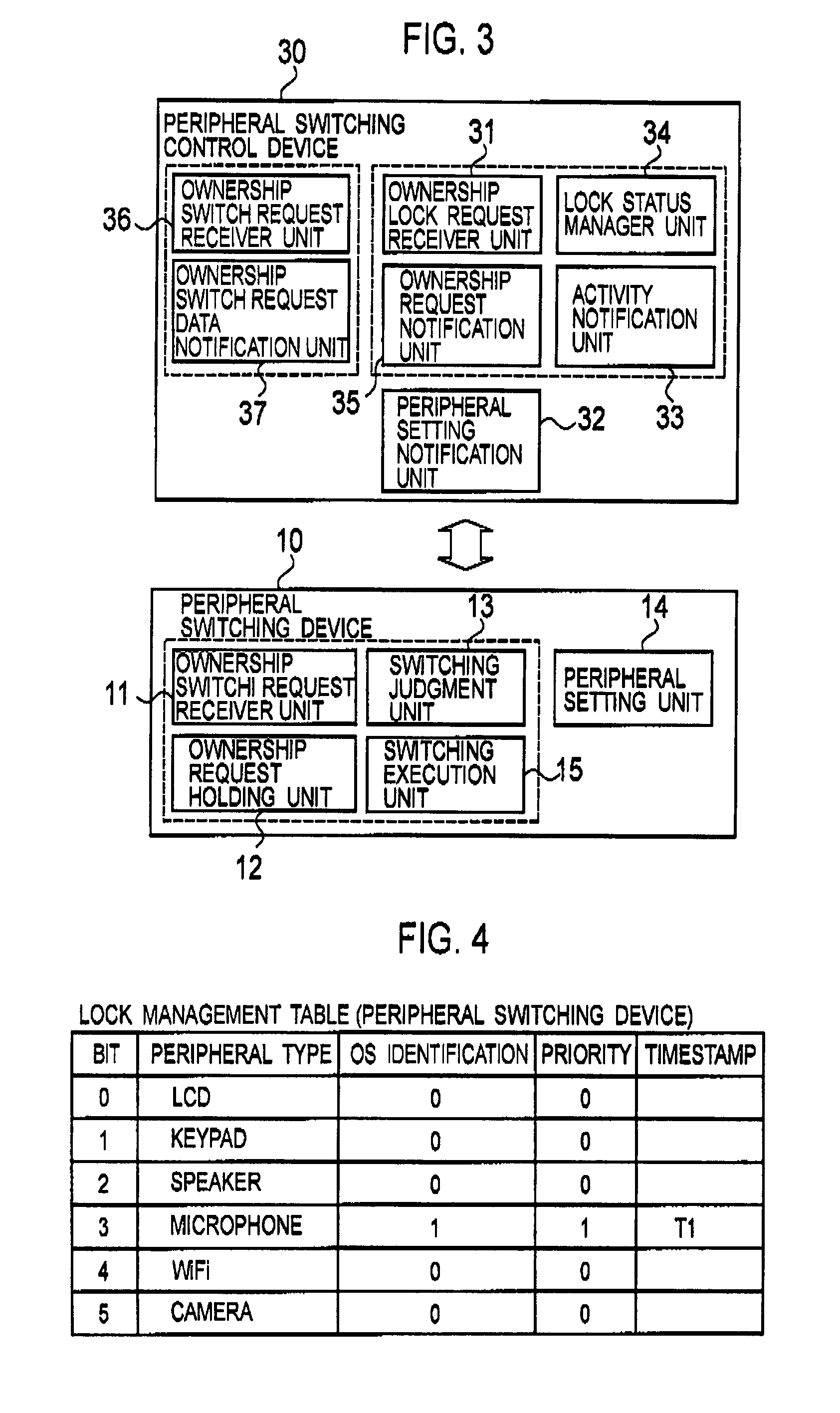
[0198]As shown in FIG. 14, in step S601, the ownership lock request receiver unit 31 receives an ownership lock request designating a peripheral type and the priority from the application, middleware or device driver.

[0199]For instance, here, assume that the ownership lock request receiver unit 31 receives an ownership lock request at a time T1 from a music playback application (the process ID=ID1), and that the ownership lock request is a request having a ...


PUM


Abstract

A peripheral switching device includes an ownership switch request receiver unit configured to receive an ownership switch request for requesting to assign a peripheral to an operating system; an ownership request holding unit configured to receive and hold an ownership request for requesting to ensure or release an ownership of a peripheral to an operating system; a switching judgment unit configured to judge whether or not to execute an assignment of a peripheral to an operating system, in accordance with the ownership switch request and the ownership request; and a switching execution unit configured to execute the assignment of the peripheral to the operating system, in accordance with the judgment result.

Description

CROSS REFERENCE TO RELATED APPLICATION[0001]This application is based upon and claims the benefit of priority from the prior Japanese Patent Applications No. 2006-202596 filed on Jul. 25, 2006, and P2007-171096 filed on Jun. 28, 2007; the entire contents of which are incorporated herein by reference.[0002]And, the entire contents of the U.S. Pat. No. 6,496,847 which are incorporated herein by reference.BACKGROUND OF THE INVENTION[0003]1. Field of the Invention[0004]The present invention relates to a peripheral switching device configured to switch an ownership of a peripheral between a plurality of operating systems that concurrently operate on a computer system.[0005]And, the present invention relates to a peripheral switching control device provided for each of a plurality of operating systems in a computer system including the peripheral switching device.[0006]2. Description of the Related Art[0007]In recent years, software such as the “Xen” and the “VMWare” has been developed an...

Claims


Application Information

Patent Timeline
Patent Type & Authority Applications(United States)
IPC IPC(8): G06F3/00
CPCG06F13/126G06F9/45533
Inventor OHTA, KENNAKAYAMA, TAKEHIROINAMURA, YU
Owner NTT DOCOMO INC
Why Eureka
Try Eureka