Ecological Liquefied Natural Gas (LNG) Vaporizer System

a technology of liquefied natural gas and vaporizer system, which is applied in the direction of gas handling/storage effect, fluid transfer, container discharge method, etc., can solve the problems of insufficient facilities designed for the regasification of other liquefied gases and inability to proceed

Inactive Publication Date: 2008-07-31
AMEC FOSTER WHEELER USA CORP
View PDF12 Cites 91 Cited by
  • Summary
  • Abstract
  • Description
  • Claims
  • Application Information

AI Technical Summary

Problems solved by technology

However, these facilities cannot proceed because of environmental concerns for using seawater as a heat transfer medium for vaporization.
Consequently, facilities designed for the regasification of other liquefied gases are inadequate for regasification of LNG.

Method used


Image

  • Ecological Liquefied Natural Gas (LNG) Vaporizer System
  • Ecological Liquefied Natural Gas (LNG) Vaporizer System

Examples


Embodiment Construction

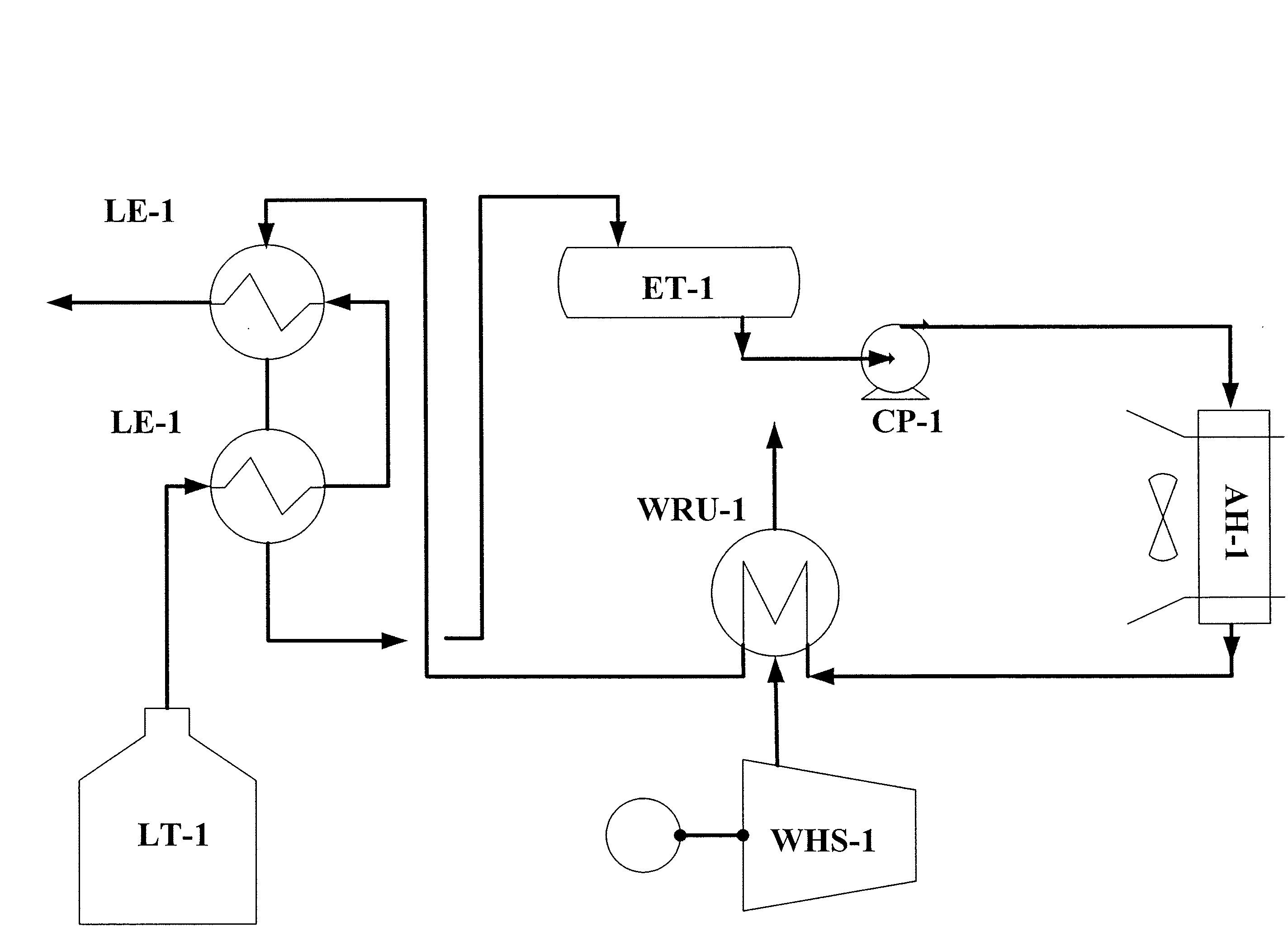
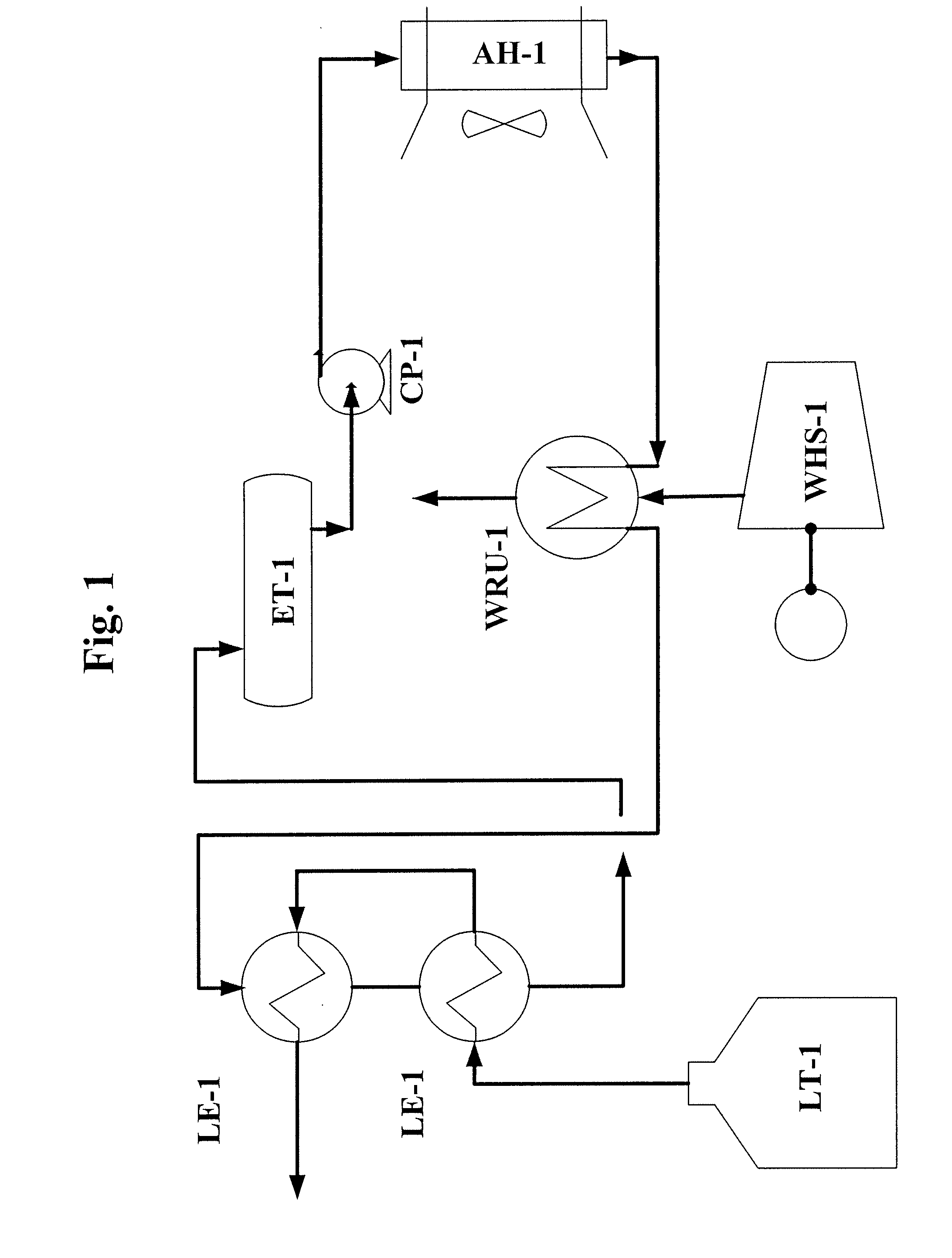
[0012]A system and method for vaporizing LNG are described. In the following description, for the purposes of explanation, numerous specific details are set forth in order to provide a thorough understanding of the present invention. It is apparent, however, to one skilled in the art that the present invention may be practiced without these specific details or with an equivalent arrangement. In other instances, well-known structures and devices are shown in block diagram form in order to avoid unnecessarily obscuring the present invention.

[0013]FIG. 1 is a diagram of a system for vaporizing LNG in accordance with an embodiment of the present invention. An expansion tank ET-1 stores a mixture of water, glycol and alcohol as a heat transfer medium. The expansion tank ET-1 comprises an atmospheric, gas-blanketed, carbon steel for heat transfer medium volume expansion and pump suction for temperatures from about 30° F. to about 150° F. at a pressure of about 10 psig. The expansion tank ...


PUM


Abstract

An approach is provided for vaporizing liquefied natural gas (LNG). A system utilizing closed circulation of a heat transfer medium heated by ambient air and waste heat from a waste heat source vaporizes the LNG.

Description

BACKGROUND OF THE INVENTION [0001]1. Field of the Invention[0002]The present invention relates to an approach for vaporizing liquefied natural gas (LNG) utilizing closed circulation of a heat transfer medium heated by ambient air and waste heat from at least one waste heat source.[0003]2. Description of the Related Art[0004]Liquefied natural gas (LNG) has been playing an important role in the recent energy market. Most major energy concerns have been aggressively developing the liquefaction facilities at remote natural gas producing locations starting from the beginning of the twenty-first century. Immediately following the completion of the liquefaction plants, receiving and regasification terminals became inevitable necessities at the energy consumer areas. There are more than 30 LNG terminals in North America. Currently, these LNG terminals have proposed using open-rack vaporization (ORV) for LNG vaporization. However, these facilities cannot proceed because of environmental conc...

Claims


Application Information

Patent Timeline
Patent Type & Authority Applications(United States)
IPC IPC(8): F17C9/02
CPCF17C9/04F17C2221/033F17C2223/0161F17C2223/033F17C2225/0123F17C2270/0136F17C2227/0313F17C2227/0323F17C2227/0393F17C2265/05F17C2225/035
Inventor DING, JAMES S.
Owner AMEC FOSTER WHEELER USA CORP
Why Eureka
Try Eureka