Integrated circuit fuse

a fuse and integrated circuit technology, applied in the field of integrated circuit fuse, can solve the problems of ic failure, more damage to surrounding materials, etc., and achieve the effect of increasing design possibilities

Inactive Publication Date: 2008-07-31
META PLATFORMS INC
View PDF12 Cites 2 Cited by
  • Summary
  • Abstract
  • Description
  • Claims
  • Application Information

AI Technical Summary

Benefits of technology

[0009]The invention includes an integrated circuit, and a fuse therefore. The integrated circuit fuses includes a plurality of terminals coupled by a fuse element, wherein the fuse element is located in a non-last metal layer and / or wherein each terminal is fully-landed on an upper surface of a wire of the fuse element. As a result, there is no explosion that causes damage to surrounding material. In addition, use of the wet etchant allows positioning of a fuse in any metal layer including any non-last metal layer, thus increasing design possibilities.
[0010]As a result, there is no explosion that causes damage to surrounding material. In addition, use of the wet etchant allows positioning of a fuse in any any non-last metal layer, thus increasing design possibilities.

Problems solved by technology

One disadvantage of this approach, however, is that the destruction of the element is explosive and oftentimes causes damage to surrounding materials, e.g., insulator.
Conventionally, damage to surrounding materials is inadequate to harm the delicate wiring at lower levels, which could cause IC failure.
Unfortunately, larger elements result in larger fuses that require more laser energy to open, and thus cause more damage to surrounding materials.
Accordingly, there is now a higher risk of damage to the delicate wiring used at the lower levels and a higher risk of IC failure.
Another disadvantage of current fuse technology is the necessity to place the fuses in the last metal layer, which limits design possibilities.

Method used


Image

  • Integrated circuit fuse
  • Integrated circuit fuse
  • Integrated circuit fuse

Examples


Embodiment Construction

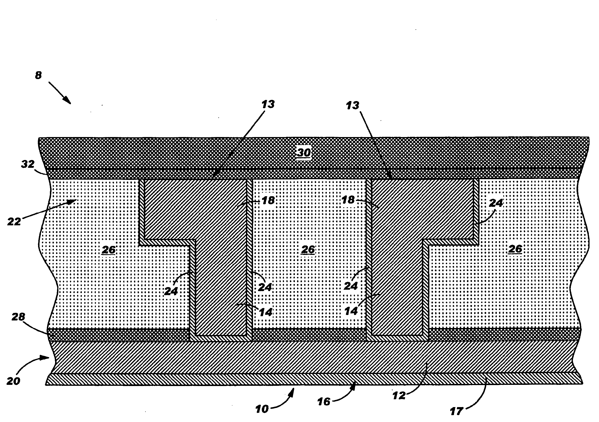
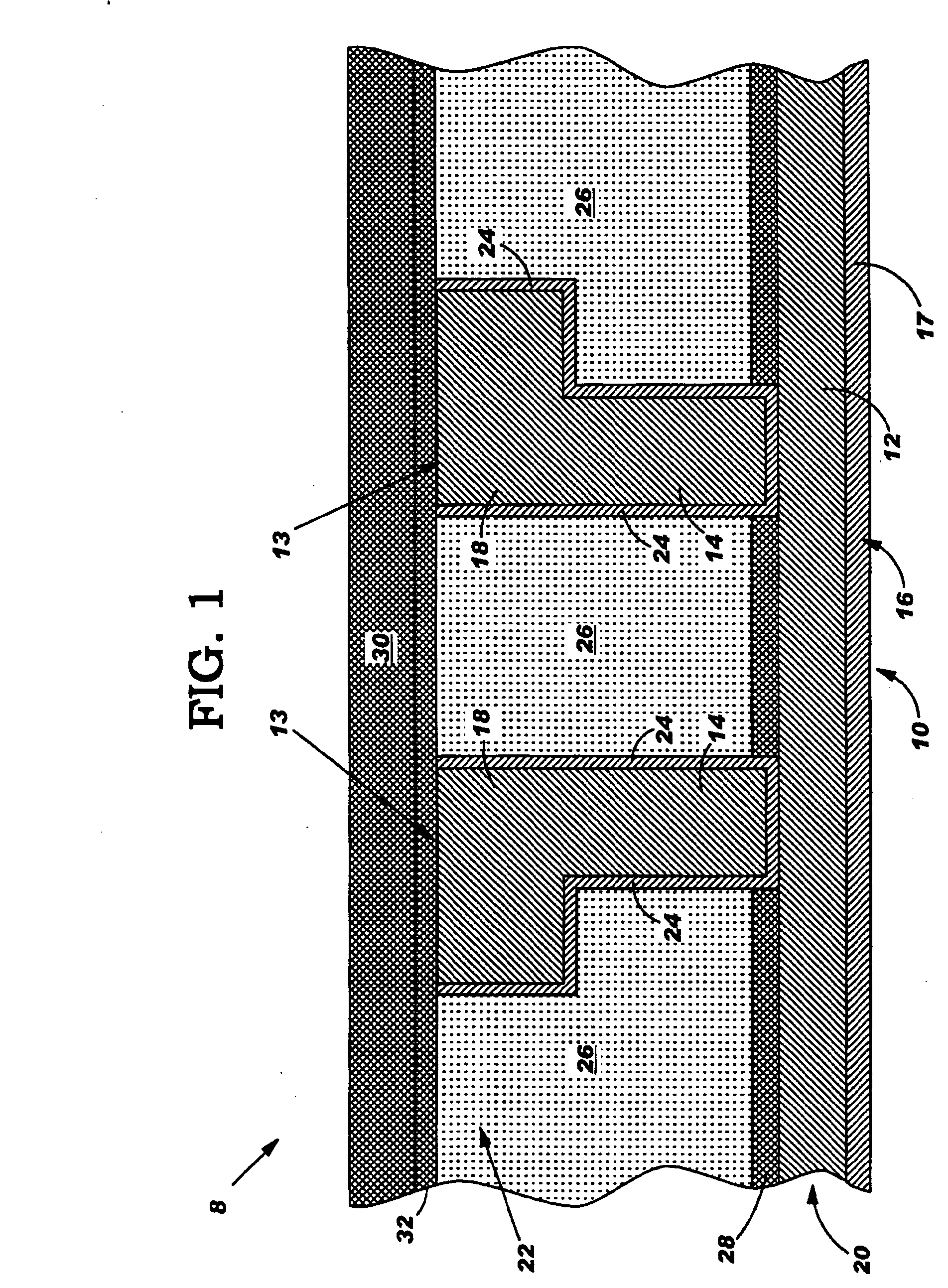
[0023]With reference to the accompanying drawings, FIG. 1 is cross-sectional view of an integrated circuit (IC) 8 including one embodiment of an IC fuse 10 according to the invention. IC fuse 10 includes a plurality of terminals 13 coupled by a fuse element 16. In the FIG. 1 embodiment, fuse element 16 is provided in the form of a horizontal wire 12 that couples terminals 13, which each include a stud 14 and a horizontal wire 18. In the FIG. 1 embodiment, terminals 13 are also located in the same layer. It is understood that each wire 18 continues on in a direction perpendicular to the page, i.e., into and / or out of the page. Each stud 14 is provided as a vertical wire and couples at least one respective wire 18 to fuse element 16. Each stud 14 and wire 18 includes a metal liner 24 of, for example, tantalum, tungsten, titanium nitride, or any other liner metal used for such purposes. Each stud 14 is fully-landed on a wire 12 of fuse element 16. That is, each metal liner 24 is on top...


PUM

PropertyMeasurementUnit
power distributionaaaaaaaaaa
areaaaaaaaaaaa
insulatingaaaaaaaaaa

Abstract

An integrated circuit and a fuse therefore are disclosed. The integrated circuit fuses includes a plurality of terminals coupled by a fuse element, wherein the fuse element is located in a non-last metal layer and / or wherein each terminal is fully-landed on an upper surface of a wire of the fuse element. As a result, there is no explosion that causes damage to surrounding material. In addition, use of the wet etchant allows positioning of a fuse in any metal layer including any non-last metal layer, thus increasing design possibilities.

Description

CROSS-REFERENCE TO RELATED APPLICATIONS[0001]This continuation application claims priority to co-pending U.S. patent application Ser. No. 10 / 604,011, entitled INTEGRATED CIRCUIT FUSE AND METHOD OF OPENING, filed on Jun. 20, 2003, the contents of which are hereby incorporated by reference in their entirety.BACKGROUND OF THE INVENTION[0002]1. Technical Field[0003]The present invention relates generally to integrated circuits, and more particularly, to an integrated circuit fuse.[0004]2. Related Art[0005]Back-end-of-line (BEOL) modifications are common in integrated circuit (IC) manufacture. One mechanism for making changes to an IC is to open a fuse that has been built into the IC. One widely used approach to opening a fuse is using a laser to destroy a fuse wire. Laser blown fuses have the advantage of allowing only selected fuses to be blown without the use of a chrome-on-glass mask. In operation, an infrared laser is used to heat a element to the point where it is destroyed, openin...

Claims


Application Information

Patent Timeline
Patent Type & Authority Applications(United States)
IPC IPC(8): H01L23/52G03F7/00H01L21/768H01L23/525
CPCH01L21/7682H01L21/76892H01L23/5256H01L2924/0002Y10S430/146H01L2924/00
Inventor GRECO, STEPHEN E.
Owner META PLATFORMS INC
Why Eureka
Try Eureka