
Method of producing shafts

a production method and technology of shafts, applied in the field of transmission, can solve the problems of complex production, low production efficiency, and low production efficiency of known shafts, and achieve the effects of improving production efficiency, facilitating production and improving handling efficiency

Active Publication Date: 2012-02-07
NEUMAYER TEKFOR ENG GMBH
View PDF23 Cites 1 Cited by
  • Summary
  • Abstract
  • Description
  • Claims
  • Application Information

AI Technical Summary

Benefits of technology

[0004]The present invention avoids the disadvantages of the previously known transmissions and their shafts and simplifies the production of transmissions and also of shafts in general, including shafts for transmissions, thereby making the production process more cost-effective and the shafts better able to be handled. In addition, the invention makes it possible to use optimum materials for individual functional sections, to save weight and thus costs of the shaft, and to expand the design possibilities of transmissions. Furthermore, due to the greatly increased flexibility in the construction of the shaft, e.g., with the combination of various gearwheels on the same shaft main body, the invention makes it possible to tailor the transmission to the particular engine characteristic and / or performance class desired.

Problems solved by technology

The entire relatively large and cumbersome part must thus be transported and therefore handled at the diverse machining points and / or machines for each of the individual machining steps, for example, and a uniform, relatively high-quality, and thus costly material must be used for all sections, which additionally represents a compromise solution, however, because the optimal materials may not be used for the individual functional points and / or sections.
These known shafts are not only, as already noted, very complex to produce, but additionally relatively costly, have a high weight, and are cumbersome to handle.
In addition, shafts of this type significantly limit the design freedom of a transmission, particularly if two such gearwheels are provided on the shaft, because no functional bodies rotatable in relation thereto, such as idlers, synchronization units, bearings, or the like, may be provided between them.

Method used


Image

  • Method of producing shafts
  • Method of producing shafts
  • Method of producing shafts

Examples


Embodiment Construction

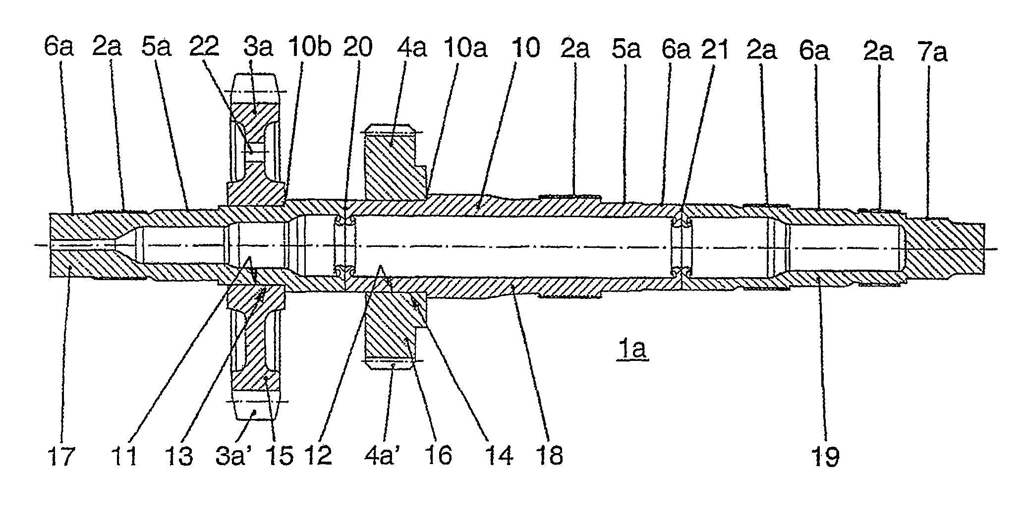
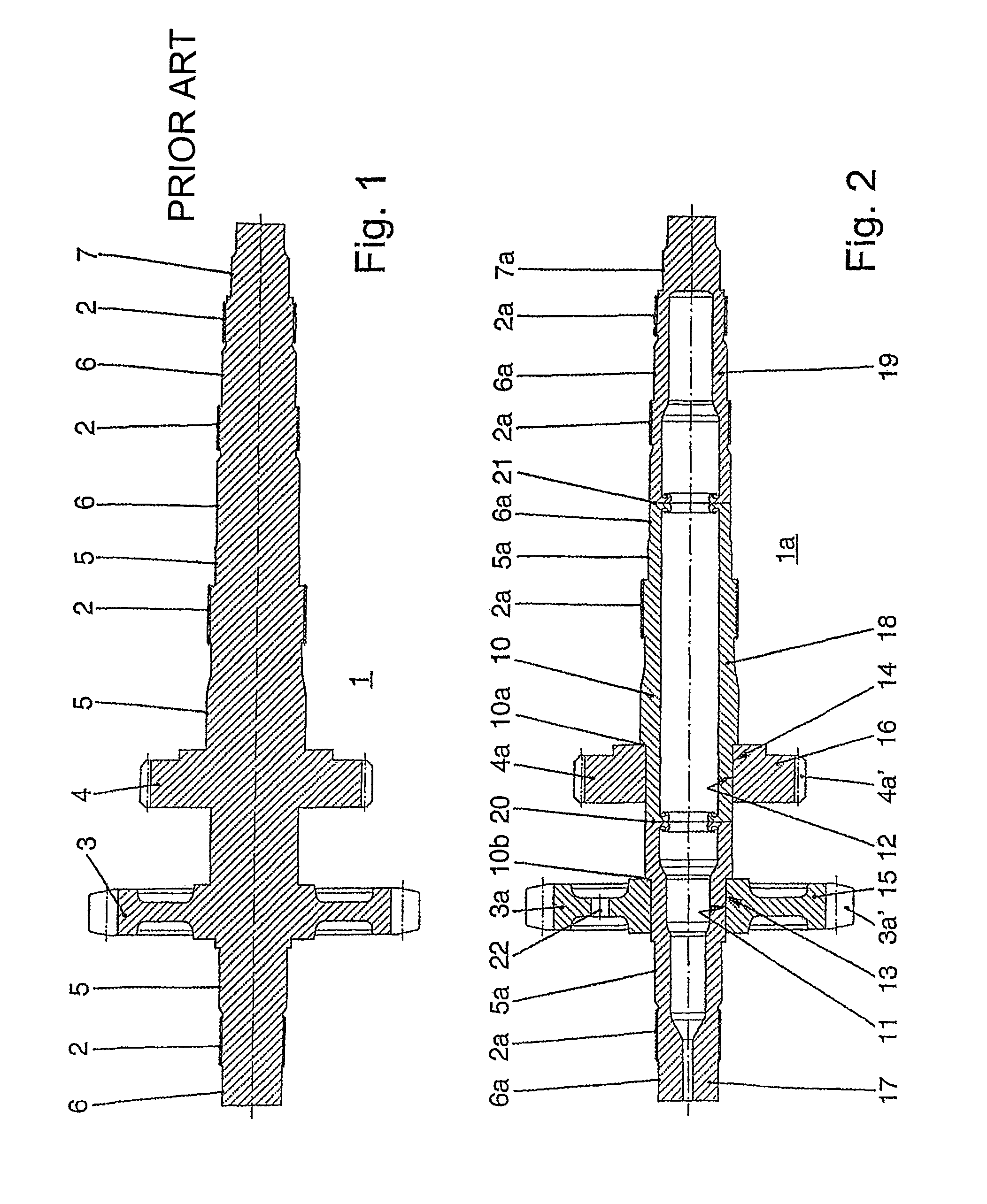
[0042]The main and / or output shaft 1 from FIG. 1 is produced in one-piece as a forged part and comprises the following machined functional bodies and / or areas: the gearing 2 for the synchronization units; the gearwheels 3 and 4; the bearing races 5 for the roller bodies, e.g., of a needle bearing for mounting the idlers; the bearing seats 6 for mounting the transmission shaft; and the thread 7 for fastening a bearing output flange.

[0043]In contrast thereto, the main or output shaft 1a according to the present invention as shown in FIG. 2 comprises a shaft main body 10 and two gearwheels 3a and 4a fastened thereon, which are each produced by themselves, i.e. separately, and subsequently are secured to the shaft 10 by being axially pressed on against an axial stop 10a, 10b, e.g., using methods and / or using tools and devices such as those described in U.S. Pat. No. 6,286,196; U.S. Pat. No. 6,804,884 and / or US 2004 / 134063 as incorporated herein by reference. Consequently, torque-fixed c...


PUM


Abstract

A method of producing shafts such as shafts used in a transmission, particularly for a motor vehicle, is provided. A shaft base body and at least one gearwheel, which is at least substantially finished separately from the shaft and subsequently is fixed to the shaft in such a way as to transmit torque available at the shaft or input torque by the gearwheel having a hollow hub body and being axially pressed onto a seat on the shaft base body so as to form a frictional connection which transmits the torque from the shaft to the gearwheel.

Description

CROSS REFERENCE TO RELATED APPLICATIONS[0001]This application is a divisional of U.S. application Ser. No. 12 / 025,339, filed Feb. 4, 2008, which is a continuation of international patent application no. PCT / DE2005 / 001587, filed Sep. 10, 2005 designating the United States of America and published in German on Feb. 8, 2007 as WO 2007 / 01537, the entire disclosure of which is incorporated herein by reference. Priority is claimed based on Federal Republic of Germany patent application no. DE 10 2005 036 681.3, filed Aug. 4, 2005.BACKGROUND OF THE INVENTION[0002]The present invention relates to a transmission, in particular for motor vehicles, having at least two shafts which transmit torque, such as main or output shaft, countershaft, or the like, each having at least one fixed gearwheel provided thereon for direct torque transmission from the gearwheel to the shaft and vice versa, as well as a method for producing such shafts.[0003]A known method for producing torque transmitting shafts...

Claims


Application Information

Patent Timeline
Patent Type & Authority Patents(United States)
IPC IPC(8): B21D53/84F16H57/00
CPCF16D1/0858F16H57/0025Y10T29/49945Y10T29/49908Y10T29/49492Y10T29/49293
Inventor VOGEL, MANFREDSZENTMIHALYI, VOLKER
Owner NEUMAYER TEKFOR ENG GMBH
Learn More