

Image processing apparatus and image displaying device
a technology of image processing and displaying device, which is applied in the direction of static indicating device, cathode-ray tube indicator, instruments, etc., can solve the problem that the merit of sub-pixel processing cannot be fully exploited, and achieve the effect of reducing color position shift and high display resolution
- Summary
- Abstract
- Description
- Claims
- Application Information
AI Technical Summary
Benefits of technology
Problems solved by technology
Method used
Image

Examples
first embodiment
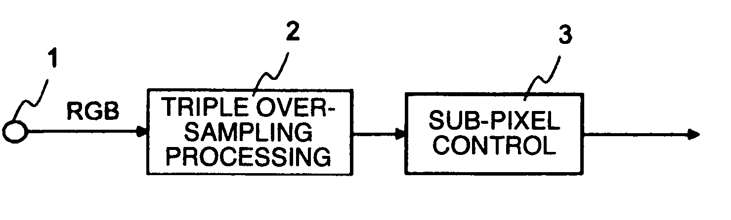
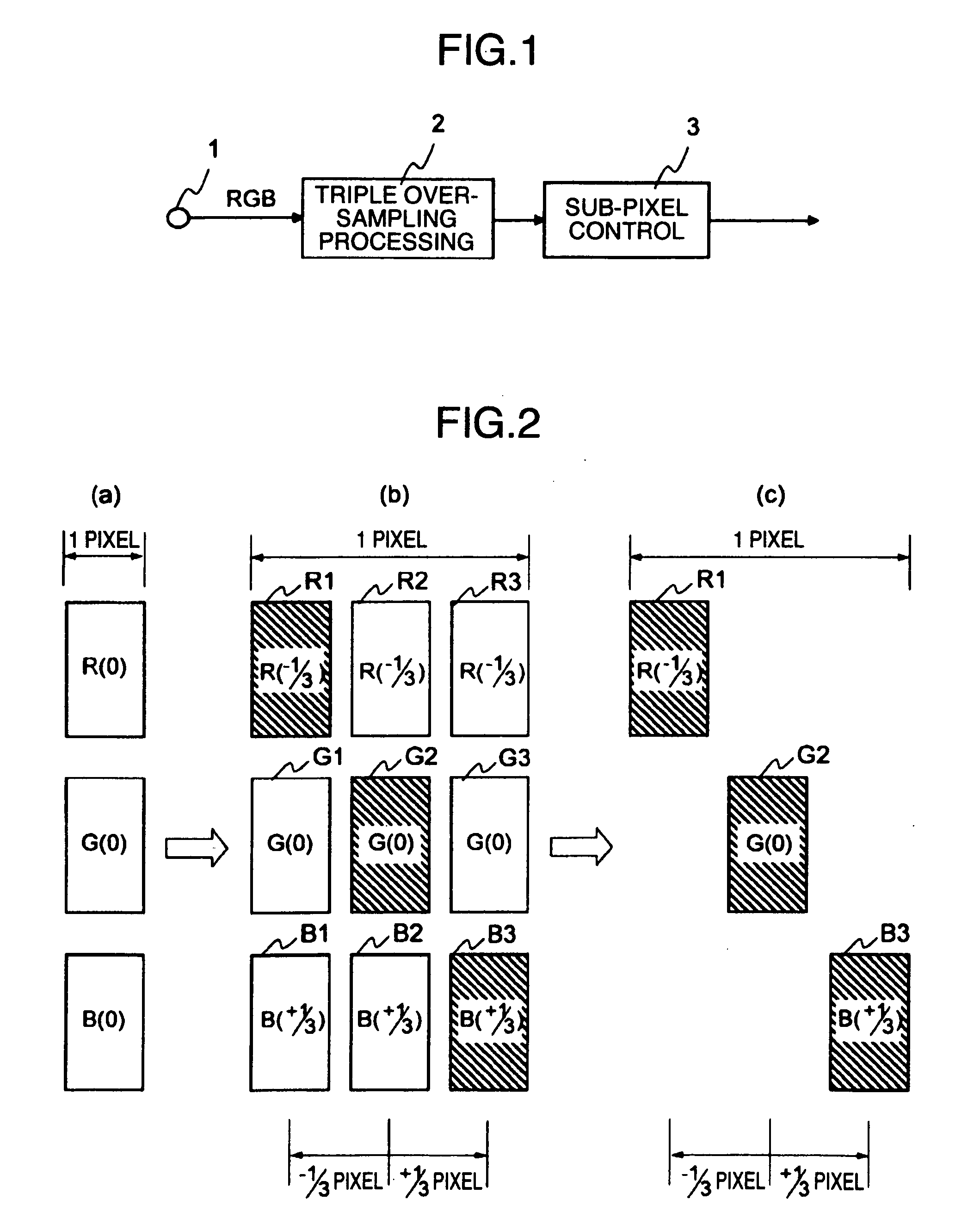
[0048]FIG. 1 is a block structural view showing an image processing apparatus according to the invention. Reference numeral 1 denotes an input terminal of an RGB image signal, reference numeral 2 denotes a triple over-sampling processing unit and reference numeral 3 denotes a sub-pixel controlling unit.
[0049]In the drawing, an R signal constituted by R sub-pixels having a digital brightness value, a G signal constituted by G sub-pixels having a digital brightness value and a B signal constituted by B sub-pixels having a digital brightness value are inputted from the input terminal 1 and are supplied to the triple over-sampling processing unit 2. The RGB sub-pixels forming the same pixel in these RGB signals are supplied at the same timing to the triple over-sampling processing unit as shown in FIG. 2(a).
[0050]The triple over-sampling processing unit 2 over-samples the RGB sub-pixels at a clock having a cycle of 1 / 3 times the pixel cycle (hereinafter called “1 / 3 pixel clock”) in sync...
second embodiment
[0091]The second embodiment that can suppress such color position shift will be hereinafter explained.
[0092]FIG. 8 is a block structural view showing an image processing apparatus according to the second embodiment of the invention. Reference numeral 1 denotes an input terminal of an RGB image signal. Reference numeral 12 denotes a triple over-sampling / sub-pixel control processing unit. Reference numeral 13 denotes a brightness signal generating unit. Reference numeral 14 denotes a brightness edge detection judgment unit. Reference numeral 15 denotes an image memory.
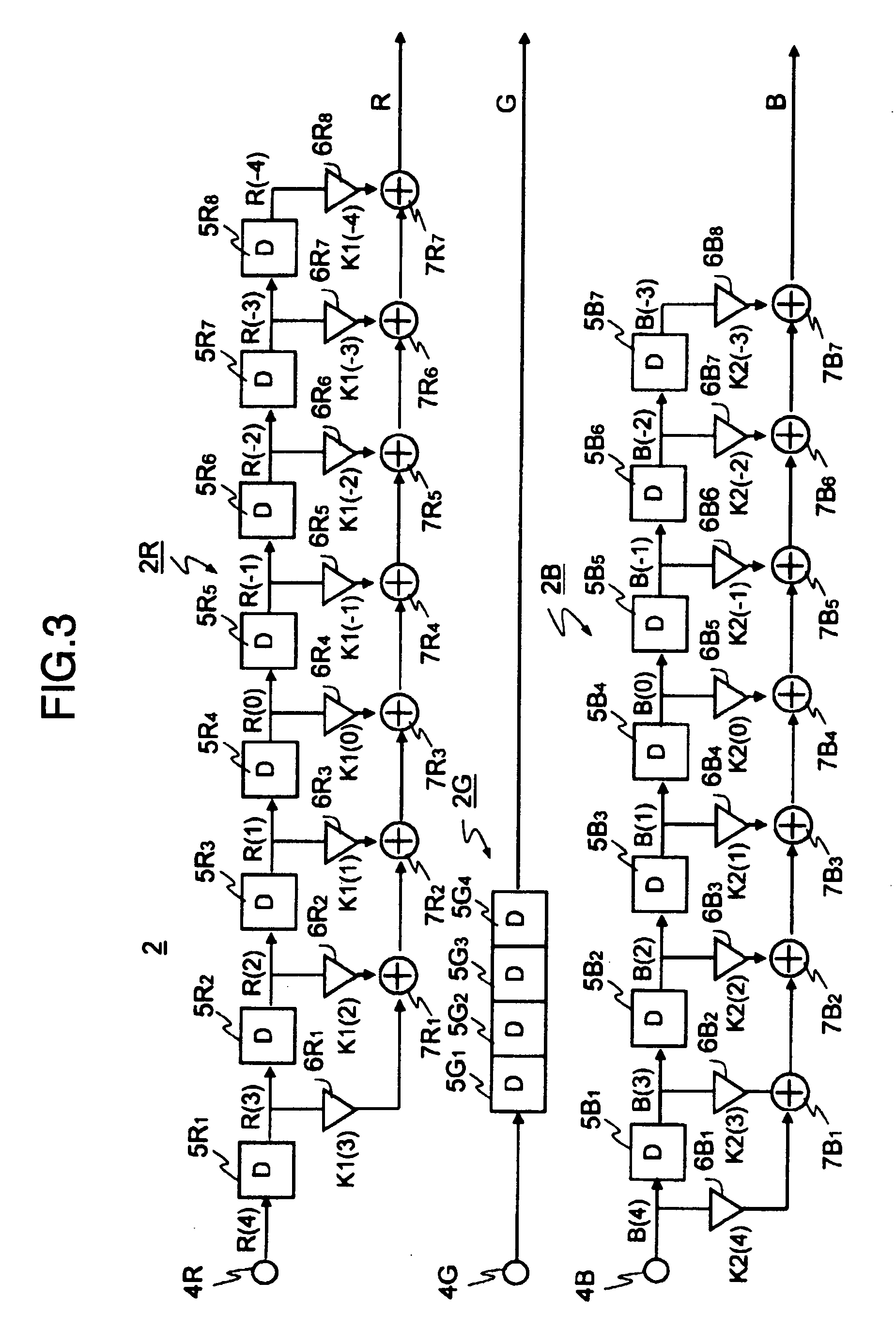
[0093]In the drawing, the triple over-sampling / sub-pixel control processing unit 12 has the construction shown in FIG. 1. However, in the triple over-sampling processing unit 2 (FIG. 1) in this triple over-sampling / sub-pixel control processing unit 12, the tap coefficients K1(n) and K2(n) used for the triple over-sampling processing and shown in FIG. 3 are variable. In this second embodiment, the tap coefficient used for...
third embodiment
[0124]FIG. 12 is a block structural view showing an image processing apparatus according to the invention. Reference numerals 24 and 25 denote signal converting units. Like reference numerals will be used to identify like constituents as in FIG. 8 and explanation of such members will be omitted.
[0125]In the drawing, a brightness signal Y, an R-Y color difference signal Cr and a B-Y color difference signal Cb are inputted from the input terminal 1. The brightness signal Y and the color difference signals Cr and Cb are supplied to the signal converting unit 24 and are converted to an RGB signal. This RGB signal is supplied to the triple over-sampling / sub-pixel control processing unit 12. The brightness signal Y inputted is also supplied to the brightness edge detection / judgment unit 15 to generate the coefficient select signal S in the same way as in the second embodiment shown in FIG. 8. The coefficient select signal S is supplied to the triple over-sampling / sub-pixel control process...
PUM
 Abstract
Description
Claims
Application Information