Gyro-sensor mounting structure in a camera having an image-stabilizing function

a technology of image stabilization and gyrosensor, which is applied in the direction of camera body details, instruments, printing, etc., can solve the problems of increasing production costs, x-axis gyro sensor and y-axis gyro sensor cannot detect camera shake with precision,

Inactive Publication Date: 2008-07-31
RICOH IMAGING COMPANY
View PDF18 Cites 15 Cited by
  • Summary
  • Abstract
  • Description
  • Claims
  • Application Information

AI Technical Summary

Benefits of technology

[0009]The present invention provides a gyro-sensor mounting structure in a camera having an image-stabilizing function, wherein the installation positions of the first and second gyro sensors to an internal mounting portion of a camera body can be easily changed even though the gyro-sensor mounting structure is simple and the gyro-sensor mounting structure is applicable to various cameras of different specifications.
[0011]Therefore, in the case where vibrations caused by movements of one or more internal movable elements of the camera are transmitted to the first gyro sensor and the second gyro sensor to exert a large influence thereupon, the installation positions of the first gyro sensor and the second gyro sensor can be easily changed by rotating the sensor mounting member at an angle of 90, 180 or 270 degrees relative to the stationary member and thereafter engaging the engaging members with the corresponding receiving portions, respectively. Moreover, in any of the four installation positions (angular positions), the first gyro sensor can surely detect rotation about one of the two axes (X and Y axes) orthogonal to each other while the second gyro sensor can surely detect rotation about the other axis.
[0013]Furthermore, the gyro-sensor mounting structure is simple, and accordingly can be achieved at a low cost.

Problems solved by technology

In addition, in the case of SLR cameras with an image-stabilizing function, vibrations created by a rotation (swing-up movement) of a quick-return mirror installed in the camera travel to the camera body or the lens barrel from the quick-return mirror when the quick-return mirror rotates since the quick-return mirror rotates (swings up) upon a shutter release button being depressed.
However, if such vibrations transmitted to the X-axis gyro sensor and the Y-axis gyro sensor exert a large influence thereupon, each of the X-axis gyro sensor and the Y-axis gyro sensor cannot detect camera shake with precision.
However, since there is only one manner of mounting a gyro-sensor mounting plate, to which the X-axis gyro sensor and the Y-axis gyro sensor are mounted, to an internal mounting portion (stationary portion) of the camera body in conventional cameras having an image-stabilizing function, i.e., since the gyro-sensor mounting plate cannot be mounted to an internal mounting portion of the camera body in any other mounting manner, the X-axis gyro sensor and the Y-axis gyro sensor together with the gyro-sensor mounting plate need to be replaced by other ones mounted to another gyro-sensor mounting plate if vibrations transmitted to the X-axis gyro sensor and the Y-axis gyro sensor through the camera body or the lens barrel exert a large influence upon the X-axis gyro sensor and the Y-axis gyro sensor.
Therefore, in the case of applying the X-axis gyro sensor and the Y-axis gyro sensor to various cameras of different specifications, it is conventionally the case that an appropriate X-axis gyro sensor and an appropriate Y-axis gyro sensor need to be selected from among various gyro sensors of different specifications for each camera, which causes an increase in the cost of production.

Method used


Image

  • Gyro-sensor mounting structure in a camera having an image-stabilizing function
  • Gyro-sensor mounting structure in a camera having an image-stabilizing function
  • Gyro-sensor mounting structure in a camera having an image-stabilizing function

Examples


Embodiment Construction

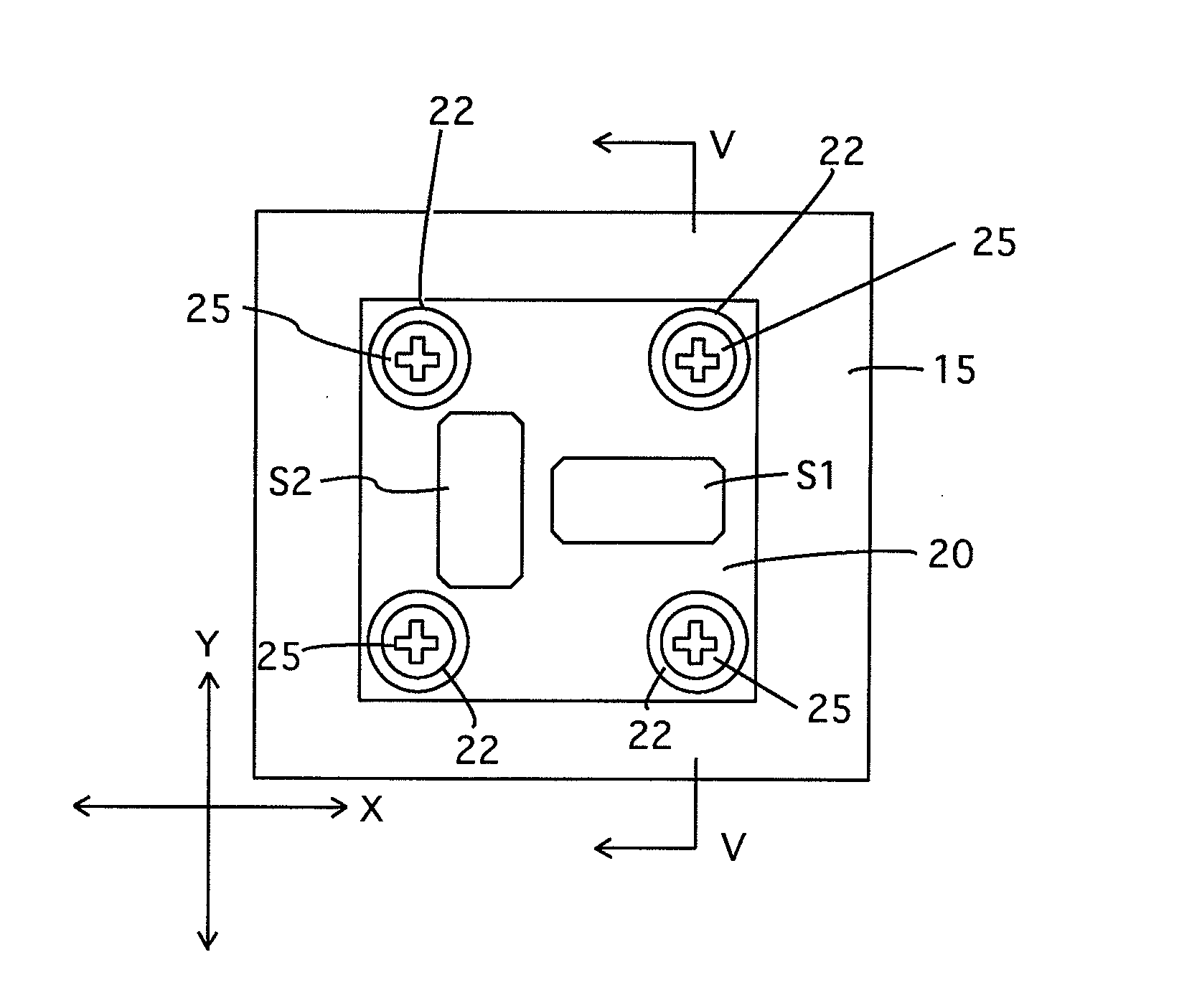
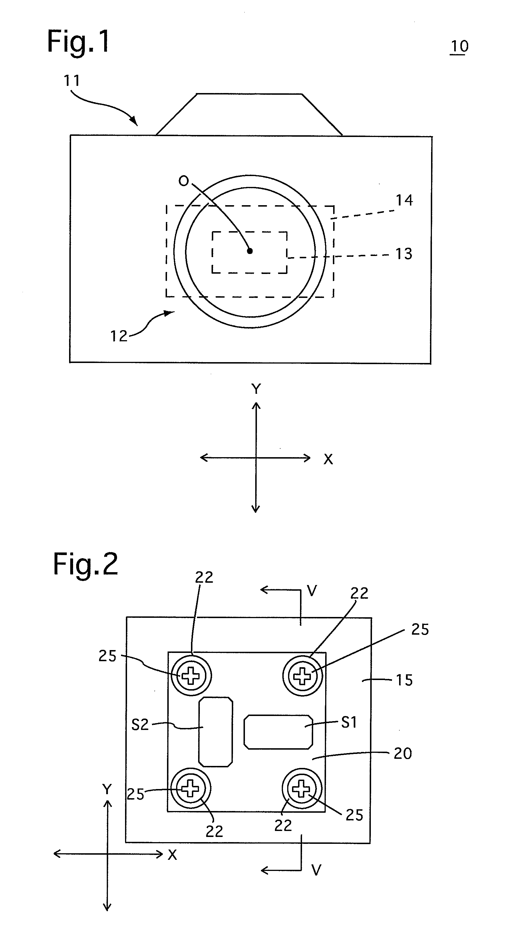
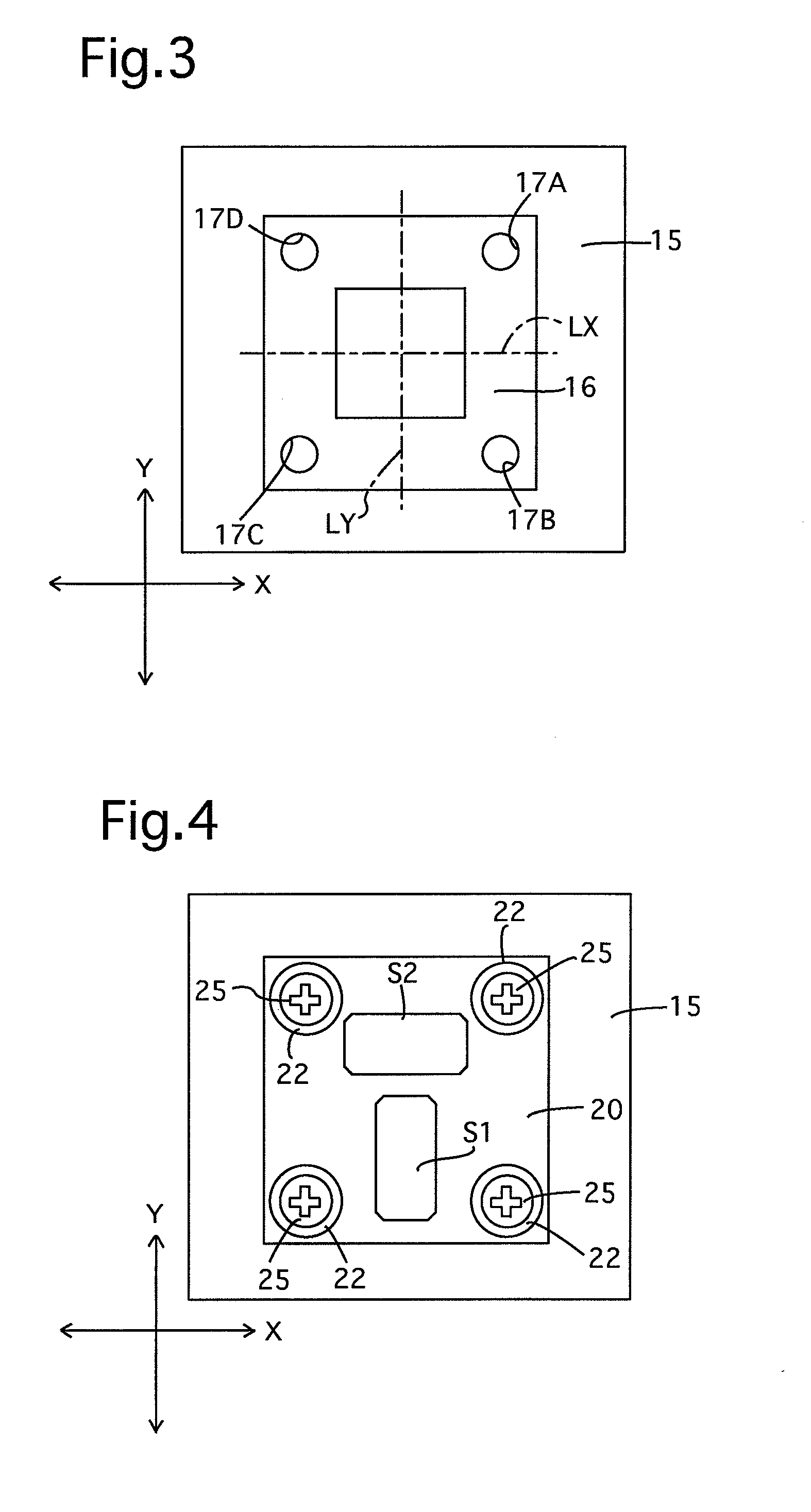
[0050]In the following description, the right / left direction and the up / down direction of an embodiment of a camera 10 having an image-stabilizing function are designated by an X-direction and a Y-direction, respectively, as shown by arrows in FIGS. 1 through 4, 6 and 7.

[0051]As shown in FIG. 1, the camera 10 that has an image-stabilizing function is an SLR camera system. The camera 10 is composed of a camera body 11 and a lens barrel (photographic lens) 12 which is detachably attached to a central portion of the front of the camera body 11. The camera body 11 is provided therein with a movable stage (movable plate) 14, the front surface of which supports an image pickup device 13. The movable stage 14 (image pickup device 13) is movable in the X and Y directions relative to the camera body 11 from an initial position shown in FIG. 1 (at which the central point of the light receiving surface of the image pickup device and an optical axis O of the lens barrel 12 coincide with each ot...


PUM


Abstract

A gyro-sensor mounting structure in a camera having an image-stabilizing function, the camera including a first gyro sensor and a second gyro sensor for detecting rotations about two axes, respectively, which are mutually orthogonal to each other and orthogonal to an optical axis of a photographic lens, the gyro-sensor mounting structure including a sensor mounting member supporting the first and second gyro sensors; a stationary member to which the sensor mounting member is fixed, positioned inside the camera; four receiving portions the sensor mounting member or the stationary member to lie in a plane orthogonal to the optical axis and be positioned at four vertexes of an imaginary square, respectively; and two, three or four engaging members supported by the other of the sensor mounting member and the stationary member and engaged with corresponding receiving portions.

Description

BACKGROUND OF THE INVENTION[0001]1. Field of the Invention[0002]The present invention relates to a camera having an image-stabilizing function, and in particular relates to a gyro-sensor mounting structure in a camera having an image-stabilizing function.[0003]2. Description of the Related Art[0004]In cameras with an image-stabilizing function (hand-shake correction function), an X-axis gyro sensor and a Y-axis gyro sensor which detect rotations (angular velocities) about an X-axis and a Y-axis to detect camera shake (hand shake) of the camera in the X-direction and the Y-direction thereof, respectively, are mounted to a gyro-sensor mounting plate. This gyro-sensor mounting plate is fixed to an internal stationary member of the camera.[0005]In such cameras with an image-stabilizing function, when a correction lens element or an image pickup device is moved to cancel out camera shake (hand shake) in directions orthogonal to the optical axis of the correction lens element or the image...

Claims


Application Information

Patent Timeline
Patent Type & Authority Applications(United States)
IPC IPC(8): G03B17/00
CPCG01C21/18G02B27/646Y10T74/12G03B2217/005G03B5/00
Inventor MOGAMIYA, MAKOTO
Owner RICOH IMAGING COMPANY
Why Eureka
Try Eureka