Server time protocol messages and methods

a server time and protocol message technology, applied in the field of time synchronization, can solve the problems of time synchronization, time synchronization, and not meeting the accuracy requirements of high-end systems, and achieve the effect of facilitating synchronization of processing units

Active Publication Date: 2008-07-31
IBM CORP
View PDF90 Cites 28 Cited by
  • Summary
  • Abstract
  • Description
  • Claims
  • Application Information

AI Technical Summary

Benefits of technology

[0005]The shortcomings of the prior art are overcome and additional advantages are provided through the provision of a method of exchanging messages for facilitating synchronization of processing units of a timing network. The method includes: generating an exchange time parameters (XTP) message command at a first processing unit, the XTP message command including a message command transmit timestamp field set by the first processing unit and a message command receive timestamp field which is unset by the first processing unit; transmitting the XTP message command to a second processing unit; setting the message command receive timestamp field in the XTP message command with the time that the XTP message command is received at the second processing unit; and generating an XTP message response at the second processing unit, the XTP message response including the message command transmit timestamp set by the first processing unit and the message command receive timestamp set by the second processing unit obtained from the XTP message command.

Problems solved by technology

This timer requires expensive dedicated timing links and a separate external box.
Other networks, such as the Network Timing Protocol (NTP), provide time synchronization, but do not meet the accuracy requirements of high-end systems.
This is a problem for those systems that do not have a capability to attach to external time servers that provide this level of accuracy.
Further, a requirement of GPS receivers or similar attachment on each system may be considered infeasible for maintenance, security and reliability reasons.

Method used


Image

  • Server time protocol messages and methods
  • Server time protocol messages and methods
  • Server time protocol messages and methods

Examples


Embodiment Construction

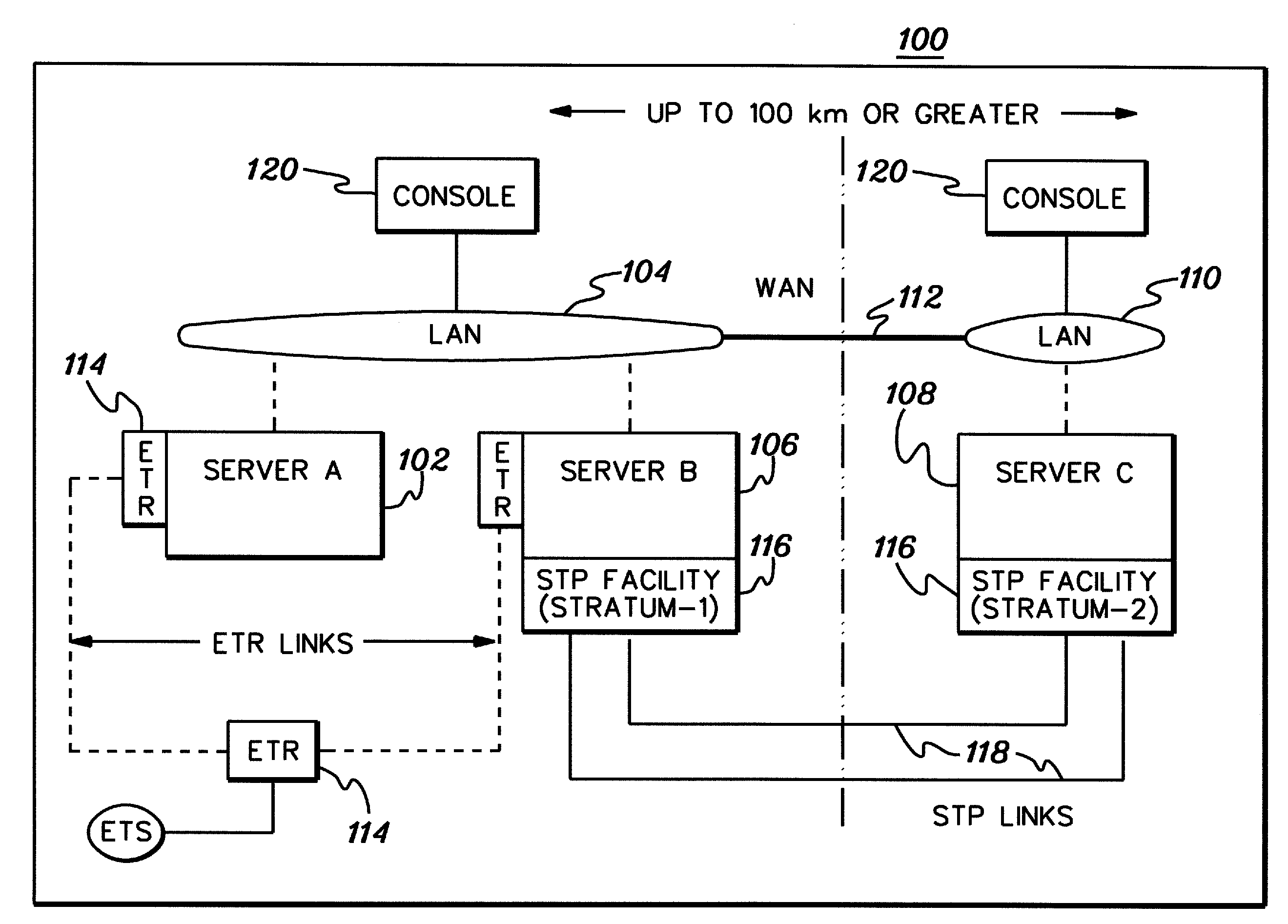
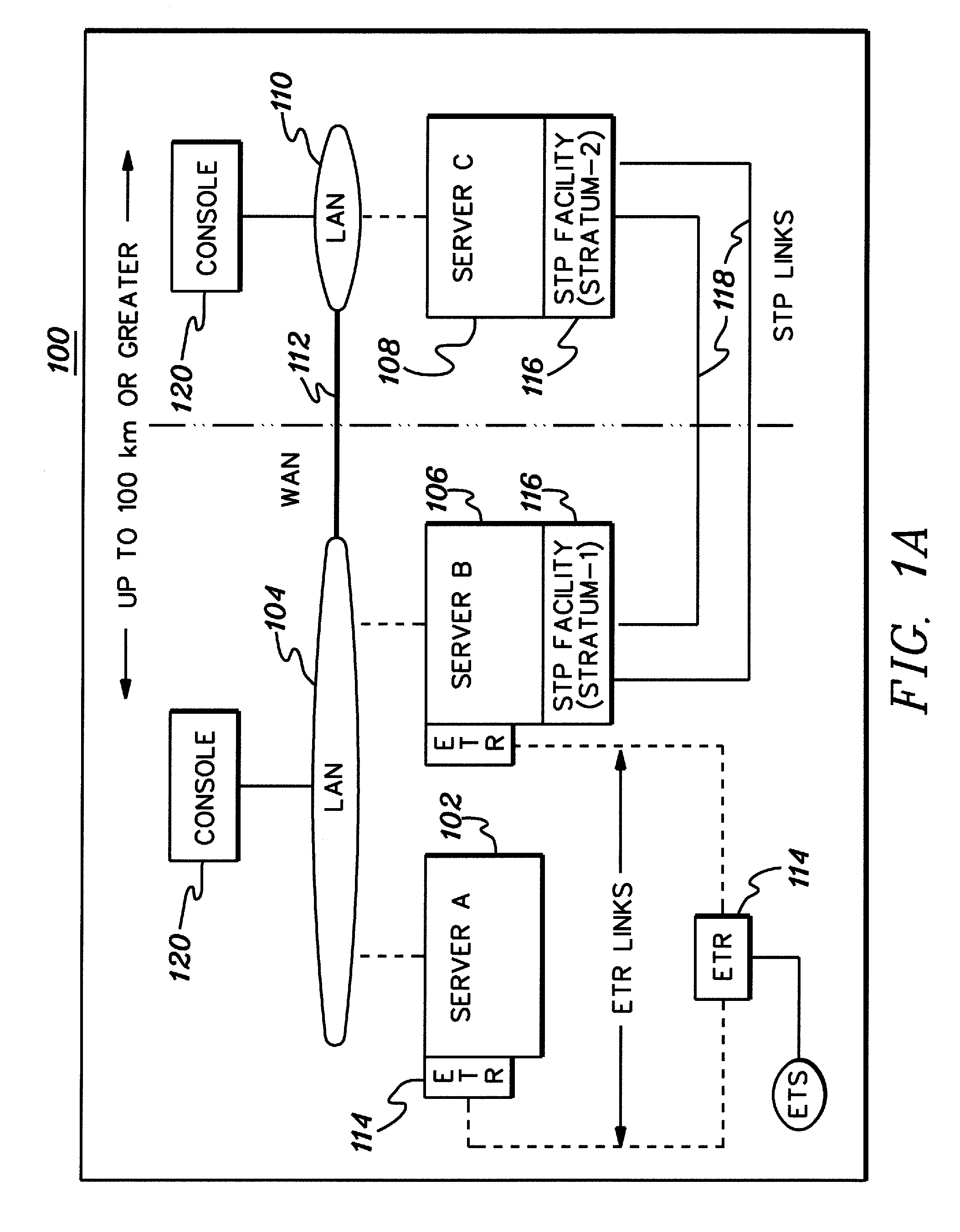
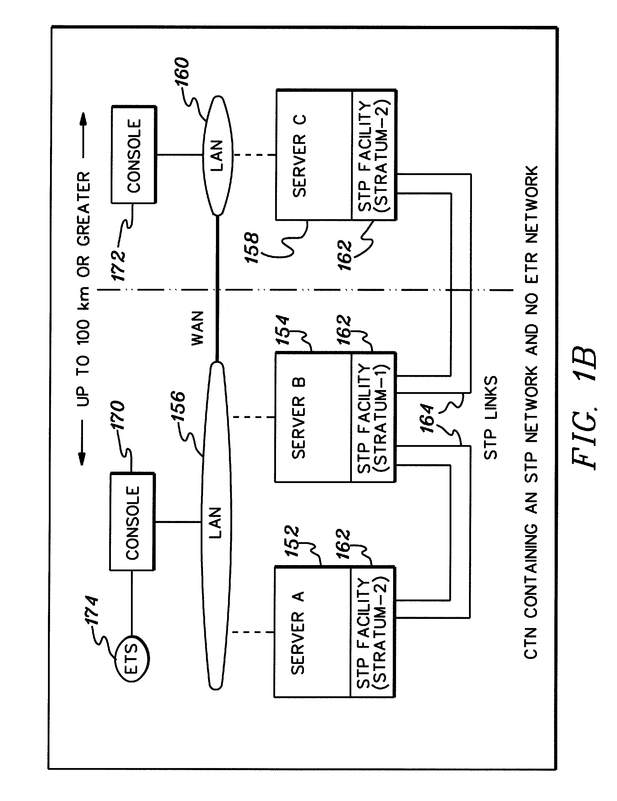
[0032]In accordance with an aspect of the present invention, server time protocol (STP) messages and processing methods employing the same are provided for, for example, transferring timing information between two servers in a timing network to facilitate synchronization thereof. Exchange time parameters (XTP) messages and STP control (STC) messages are described.

[0033]Although various networks can be configured to include a stratum-1 server, one such network is a Coordinated Timing Network (CTN). In a Coordinated Timing Network, multiple distinct computing systems maintain time synchronization to form the Coordinated Timing Network. Systems in the Coordinated Timing Network employ a message based protocol, referred to as a Server Time Protocol (STP), to pass timekeeping information between the systems over existing, high-speed data links. This enables the time of day (TOD) clocks at each system to be synchronized to the accuracy required in today's high-end computing systems. Since...


PUM


Abstract

Server time protocol (STP) messages and methods of exchange thereof are provided for facilitating synchronization of processing units of a timing network. The STP messages include exchange time parameters (XTP) commands and responses, and STP control (STC) commands and responses. XTP message exchange processing includes: generating an XTP message command at a first processing unit including a command transmit timestamp field set by the first processing unit and a command receive timestamp field which is unset by the first processing unit; transmitting the XTP message command to a second processing unit; setting the command receive timestamp field in the XTP command with the time the XTP command is received at the second processing unit; and generating an XTP message response at the second processing unit, the message response including the command transmit timestamp set by the first processing unit and the command receive timestamp set by the second processing unit.

Description

CROSS-REFERENCE TO RELATED APPLICATIONS[0001]This application claims priority to U.S. Provisional Application No. 60 / 887,512, entitled “Server Time Protocol Messages and Methods”, filed Jan. 31, 2007, which is hereby incorporated herein by reference in its entirety.TECHNICAL FIELD[0002]This invention relates in general to time synchronization within and across a network of processing units, and more particularly, to server time protocol messages and methods that facilitate servers in a timing network synchronizing, for example, to a same root primary reference time.BACKGROUND OF THE INVENTION[0003]For performance and data integrity reasons, computing systems that access shared data, such as SYSPLEX offered by International Business Machines Corporation, Armonk, N.Y., must be able to maintain time of day (TOD) clock synchronization to an accuracy that is better than best case communication time between the systems. Currently, in one example, to meet the synchronization requirements, ...

Claims


Application Information

Patent Timeline
Patent Type & Authority Applications(United States)
IPC IPC(8): G06F15/16
CPCH04J3/0641H04J3/0667H04L67/00H04L43/106H04L43/0864H04J3/06
Inventor CARLSON, SCOTT M.CRABTREE, DONALDDAHLEN, DENNIS J.DHONDY, NOSHIR R.HACK, MICHEL H.T.SEVIGNY, DENISE M.SMITH, RONALD M.WIERBOWSKI, JUDITH A.
Owner IBM CORP
Why Eureka
Try Eureka