Method of manufacturing magnetic head, and magnetic head substructure

a technology of which is applied in the field of manufacturing magnetic head and substructure, can solve the problems of reducing the yield of magnetic head, difficult to solve the above-mentioned problem, and difficult to precisely detect the distance between the lapped surface and the target position of the medium facing surface, so as to achieve the effect of precise detection

Active Publication Date: 2008-08-07
HEADWAY TECH INC +2
View PDF10 Cites 0 Cited by
  • Summary
  • Abstract
  • Description
  • Claims
  • Application Information

AI Technical Summary

Benefits of technology

[0019]It is an object of the invention to provide a method of manufacturing a magnetic head and a magnetic head substructure that allow a medium facing surface to be formed at a desired position with accuracy when the medium facing surface is formed by lapping a surface to be the medium facing surface, and that allow p

Problems solved by technology

As thus described, the conventional problem is that there are some cases in which the portion of the medium facing surface at which the end face of the track width defining portion is exposed deviates from its desired position to thereby cause the track width to be of a value other than the desired value, and as a result, the yield of magnetic heads is reduced.
According to the technique disclosed in U.S. Pat. No. 5,742,995, it is possible to calculate the MR height but it is impossible to solve the above-mentioned problem.
The following problem arises when the position of the lapped surface is detected while monitoring the resistances of the MR elements or the resistances of the resistor elements disclosed in U.S. Patent Application Publication US2006/017

Method used


Image

  • Method of manufacturing magnetic head, and magnetic head substructure
  • Method of manufacturing magnetic head, and magnetic head substructure
  • Method of manufacturing magnetic head, and magnetic head substructure

Examples


first embodiment

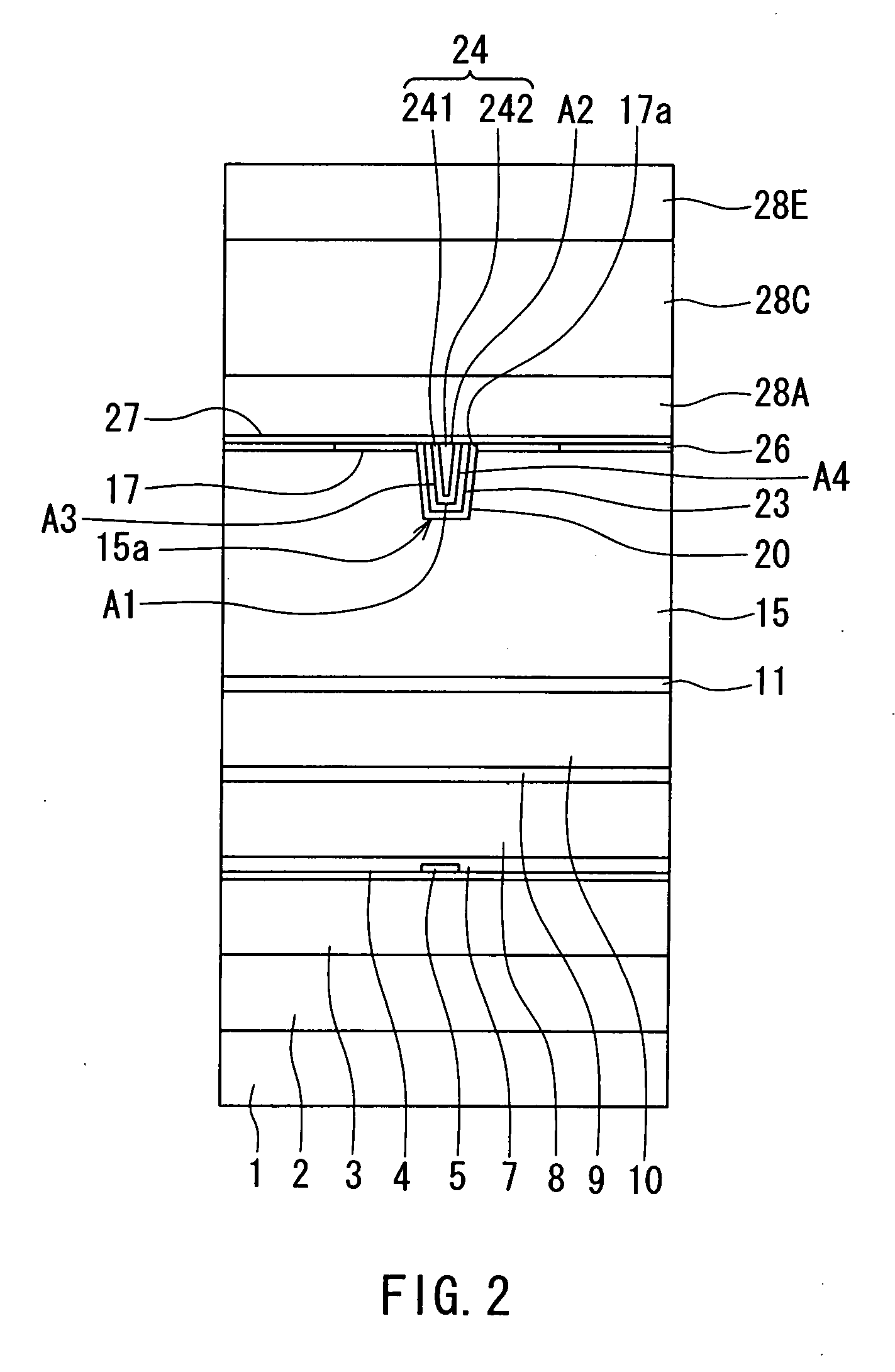
[0085]Preferred embodiments of the invention will now be described in detail with reference to the accompanying drawings. Reference is now made to FIG. 2 and FIG. 3 to describe the configuration of a magnetic head manufactured through the use of a manufacturing method and a magnetic head substructure of a first embodiment of the invention. Here, a magnetic head for the perpendicular magnetic recording system will be described as an example of the magnetic head. FIG. 2 is a front view for illustrating the medium facing surface of the magnetic head. FIG. 3 is a cross-sectional view for illustrating the configuration of the magnetic head. FIG. 3 illustrates a cross section orthogonal to the medium facing surface and a surface of a substrate. The arrow indicated with T in FIG. 3 shows the direction of travel of a recording medium.

[0086]As shown in FIG. 2, the magnetic head of the embodiment has a medium facing surface 40 that faces toward a recording medium. As shown in FIG. 2 and FIG. ...

modification example

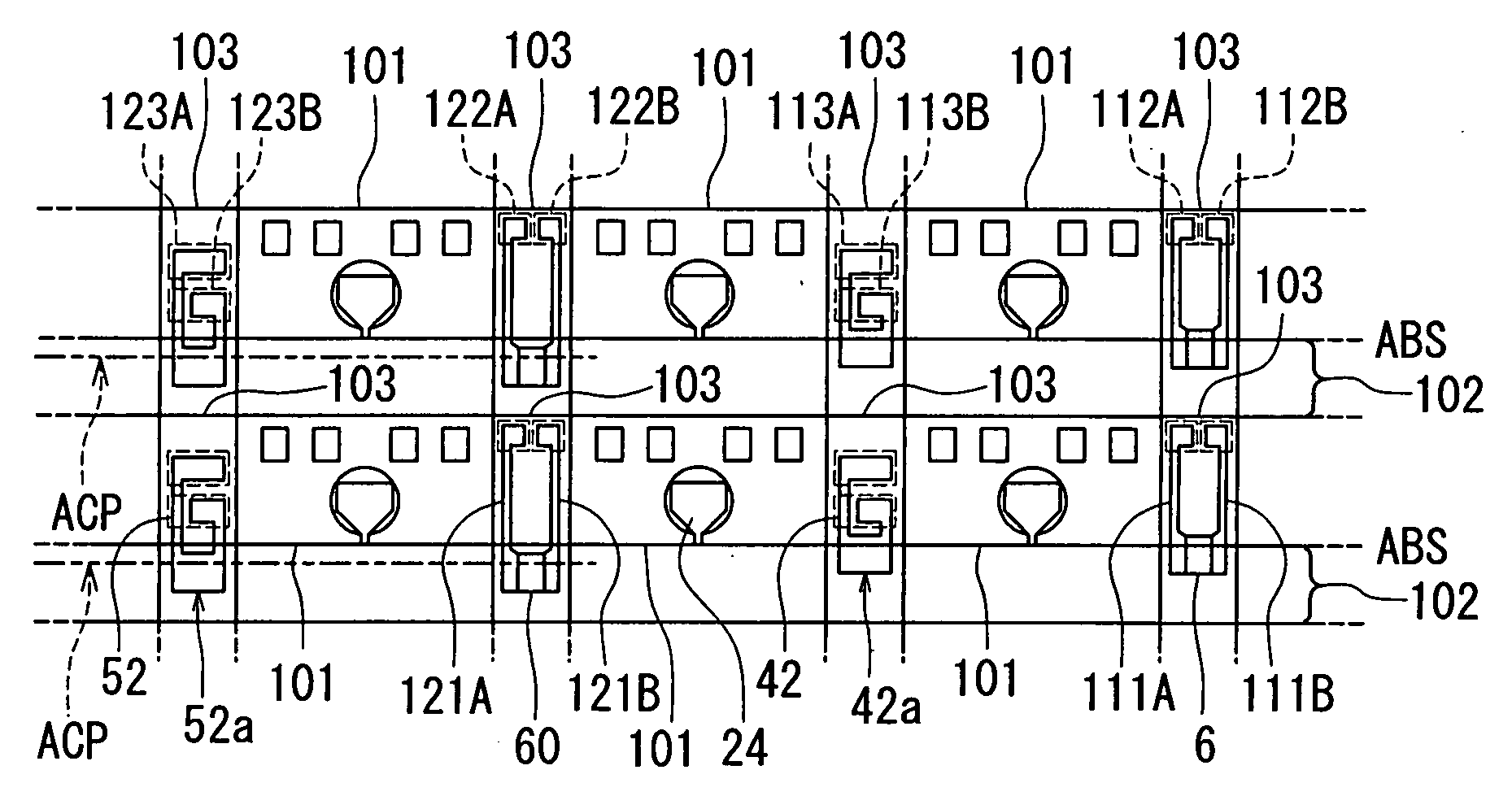
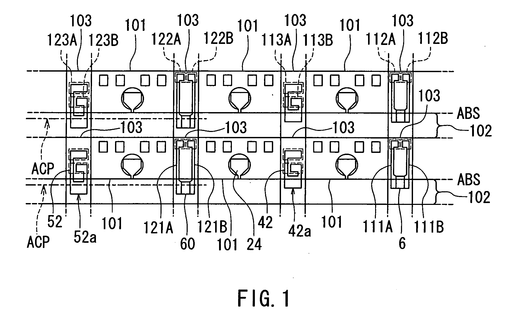
[0209]FIG. 49 illustrates a modification example of the magnetic head substructure of the embodiment. In the modification example each of the first resistor element 6 and the second resistor element 42a is disposed to extend across the pre-head portion 101 and a portion of the inter-row portion to be removed 102 that are adjacent to each other with the plane ABS disposed in between. That is, a portion of each of the first resistor element 6 and the second resistor element 42a is located in a region that will remain in the magnetic head. The two leads 111A and 111B connected to the first resistor element 6 are located in the pre-head portion 101. A portion of the resistor layer 42 other than the second resistor element 42a is located in the pre-head portion 101, too. In addition, the two terminals 112A and 112B respectively connected to the leads 111A and 111B and the two terminals 113A and 113B connected to the resistor layer 42 are located in the pre-head portion 101, too.

[0210]In ...

second embodiment

[0212]Reference is now made to FIG. 50 to describe a method of manufacturing a magnetic head and a magnetic head substructure of a second embodiment of the invention. The magnetic head substructure of the second embodiment incorporates first to fourth detection elements, wherein at least one of the first to fourth detection elements has an indicator section 410 shown in FIG. 50. That is, in the substructure of the second embodiment, the indicator section 410 shown in FIG. 50 is provided in place of at least one of the first to fourth resistor elements 6, 42a, 60 and 52a of the first embodiment. The indicator section 410 is placed at a position the same as that of the resistor elements 6, 42a, 60 and 52a. The indicator section 410 may be located in a region that will not remain in the magnetic head, or a portion of the indicator section 410 may be located in a region that will remain in the magnetic head.

[0213]If the indicator section 410 is provided in place of the resistor elements...


PUM

PropertyMeasurementUnit
Magnetic fieldaaaaaaaaaa
Electrical resistanceaaaaaaaaaa
Widthaaaaaaaaaa

Abstract

Components of a plurality of magnetic heads are formed on a single substrate to fabricate a magnetic head substructure in which a plurality of pre-head portions are aligned in a plurality of rows. The substructure is cut to separate the plurality of pre-head portions from one another, and the plurality of magnetic heads are thereby fabricated. The surface formed by cutting the substructure is lapped to form a lapped surface. The lapped surface is lapped so as to reach a target position of a medium facing surface. The substructure incorporates first to fourth resistor elements each of which detects the position of the lapped surface. The third and fourth detection elements are located at positions shifted from the first and second resistor elements along the direction orthogonal to the medium facing surface.

Description

BACKGROUND OF THE INVENTION[0001]1. Field of the Invention[0002]The present invention relates to a method of manufacturing magnetic heads used for writing data on a recording medium and to a magnetic head substructure used for manufacturing the magnetic heads.[0003]2. Description of the Related Art[0004]The recording systems of magnetic read / write devices include a longitudinal magnetic recording system wherein signals are magnetized in the direction along the surface of the recording medium (the longitudinal direction) and a perpendicular magnetic recording system wherein signals are magnetized in the direction perpendicular to the surface of the recording medium. It is known that the perpendicular magnetic recording system is harder to be affected by thermal fluctuation of the recording medium and capable of implementing higher linear recording density, compared with the longitudinal magnetic recording system.[0005]For each of the longitudinal magnetic recording system and the per...

Claims


Application Information

Patent Timeline
IPC IPC(8): G11B5/127
CPCG11B5/1278G11B5/3116G11B5/3166G11B5/3169G11B5/3173Y10T29/49046Y10T29/49052Y10T29/49048Y10T29/49041Y10T29/49037Y10T29/49034G11B5/3967
Inventor SASAKI, YOSHITAKAITOH, HIROYUKIISHIZAKI, KAZUOFUJII, RYUJISHIMIZU, TATSUSHI
Owner HEADWAY TECH INC
Why Eureka
Try Eureka