Rotary Union Assembly For Use In Air Pressure Inflation Systems For Tractor Trailer Tires

a technology of air pressure inflation and rotary unions, which is applied in the direction of hubs, mechanical equipment, transportation and packaging, etc., can solve the problems of oil leakage, difficult and awkward access to the elements comprising the rotary union, and the useful life of the rotary union assembly employed in these systems is relatively limited, so as to prevent pressure buildup

Inactive Publication Date: 2008-08-07
AIRGO IP
View PDF19 Cites 30 Cited by
  • Summary
  • Abstract
  • Description
  • Claims
  • Application Information

AI Technical Summary

Benefits of technology

[0008]In both pressurized and non-pressurized axle applications, the rotary union housing is sealably secured against the exterior surface of the end wall of the hubcap so as to be rotatable with the hubcap and tire. The annular seal in the plug assembly forms an airtight seal about an upstream position of the tubular conduit which is preferably rigid to prevent distortion of the conduit over time. In addition, the annular seal allows for the length of the rigid portion of the tubular conduit projecting from the annular seal toward the rotary union housing to be readily varied by the simple insertion or retraction of the conduit from the plug assembly during installation, thereby accommodating wide variations and hubcap configurations without the need for part replacement and without adversely affecting the integrity of the seal. As both the tubular conduit and the annular seal through which it extends are stationary and the portion of the tubular conduit which the annular seal engages is rigid, wear it is virtually eliminated at this juncture of the assembly.
[0009]In a preferred embodiment of the invention, a portion of the tubular conduit between the plug assembly and rotary union housing is flexible. Thus, inadvertent off center mountings of the rotary housing relative to the threaded fitment on the axle spindle is readily accommodated without significantly affecting either the integrity or the life of the air seals in the assembly. Positioning the rotary housing against the exterior end surface of the hub cap locates the rotary seal formed therein outside of the lubrication compartment of the wheel and thereby prevents pressure build ups within the lubrication compartment in the event of air leakage in the rotary seal.
[0012]A pressure relief valve system comprising at least one calibrated poppet valve is provided in the rotary union housing for venting both the rotary union and the lubrication compartment to atmosphere to avoid pressurizing the bearings within the housing in the event of a leak in the rotary union seal and to prevent a pressure build up within the lubrication compartment in the event of an air leak in the tire inflation system upstream of the rotary union seal. The valve system is configured to prevent outside water from entering into the hub in the event the rotary union housing is submerged in water or is subjected to high pressure washing and to resist oil from the lubrication compartment within the hub cap from passing therethrough and onto the vehicle wheels while discharging air therethrough.

Problems solved by technology

Pressure responsive valves are employed between each rotary union assembly and its associated tires so that upon the occurrence of a leak in one of the tires, the resulting pressure loss will cause one of the valves to open and allow air flow from the rotary union assembly to pass there through to the leaking tire.
While these central tire inflation systems are well known and in widespread use, they suffer from several shortcomings.
The rotary union assemblies employed in these systems have a relatively limited useful life span before the rotary seals begin to leak.
Accordingly, any air leakage in the rotary union seals causes an air pressure build up within the lubrication compartment which can damage the oil seals therein, and create an oil leak.
If the wheel bearings loose their lubrication, they will seize up and can cause a fire.
In addition to creating the potential for a dangerous fire, the positioning of the rotary union within the lubrication compartment of the wheel makes accessibility to the elements comprising the rotary union both difficult and awkward.
As a result, the costs of repair and replacement are significantly increased.
Other problems facing central tire inflation systems include a lack of uniformity in tractor trailer wheel hub cap configurations and off center mountings.

Method used


Image

  • Rotary Union Assembly For Use In Air Pressure Inflation Systems For Tractor Trailer Tires
  • Rotary Union Assembly For Use In Air Pressure Inflation Systems For Tractor Trailer Tires
  • Rotary Union Assembly For Use In Air Pressure Inflation Systems For Tractor Trailer Tires

Examples


Embodiment Construction

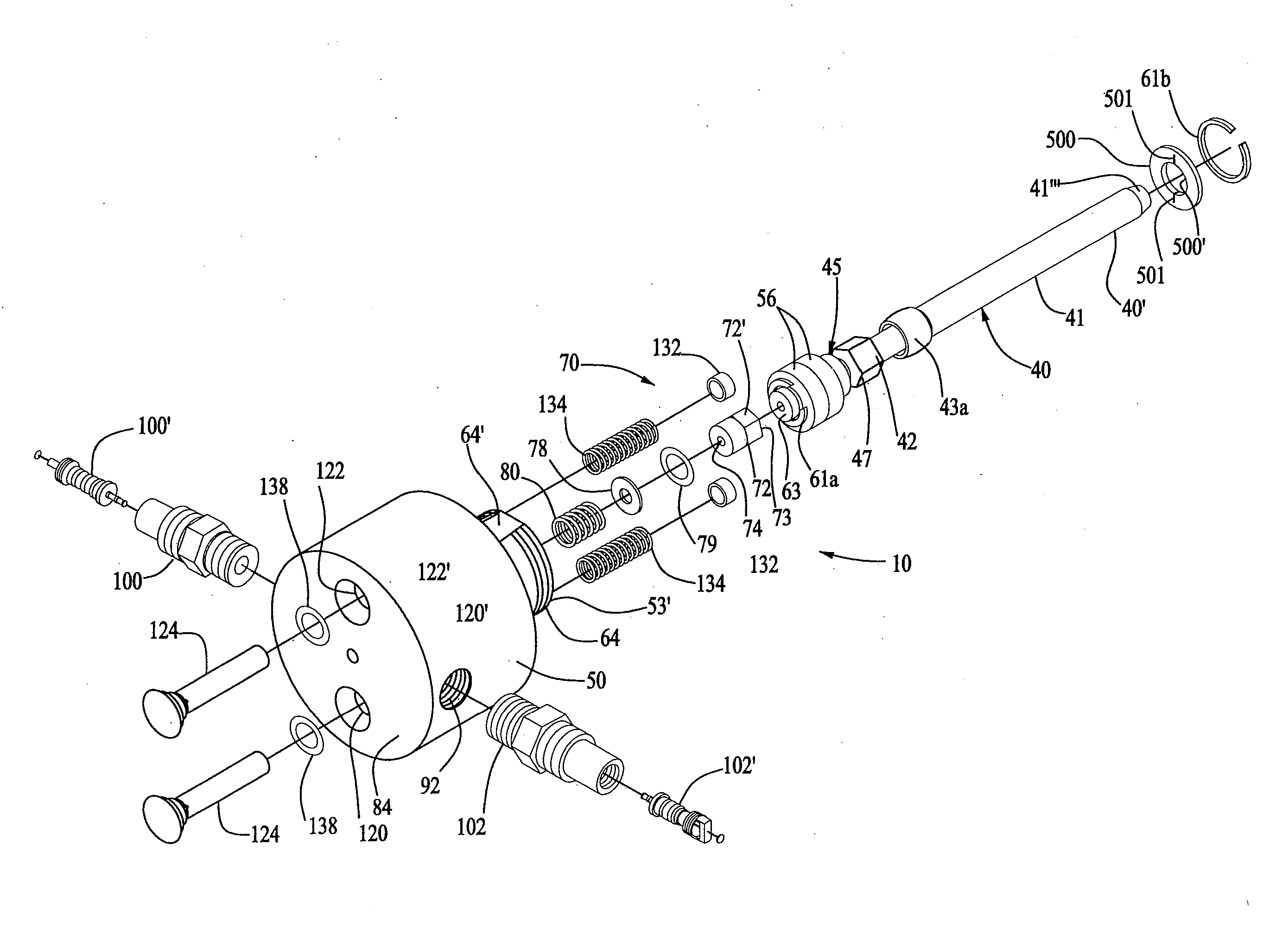
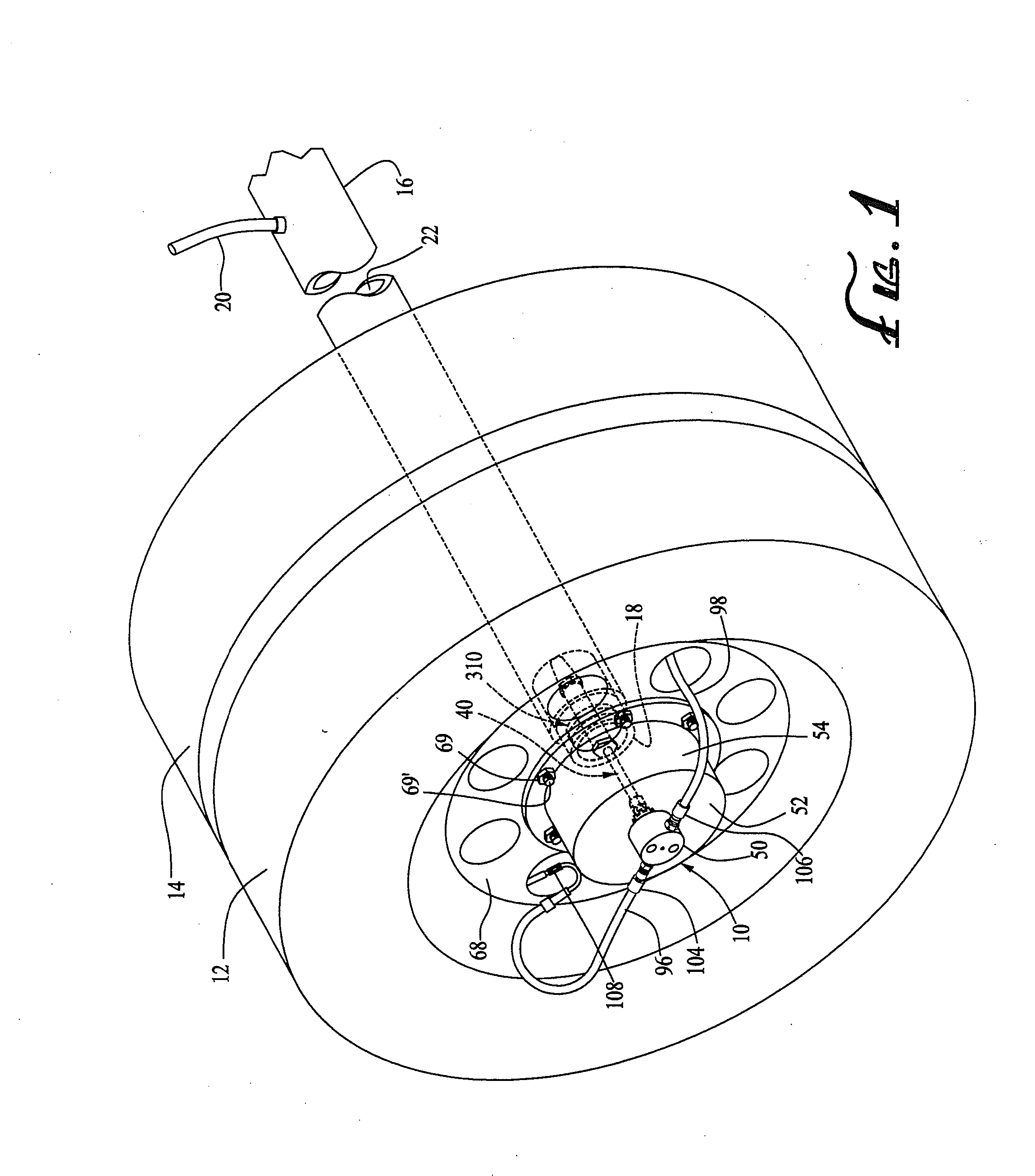
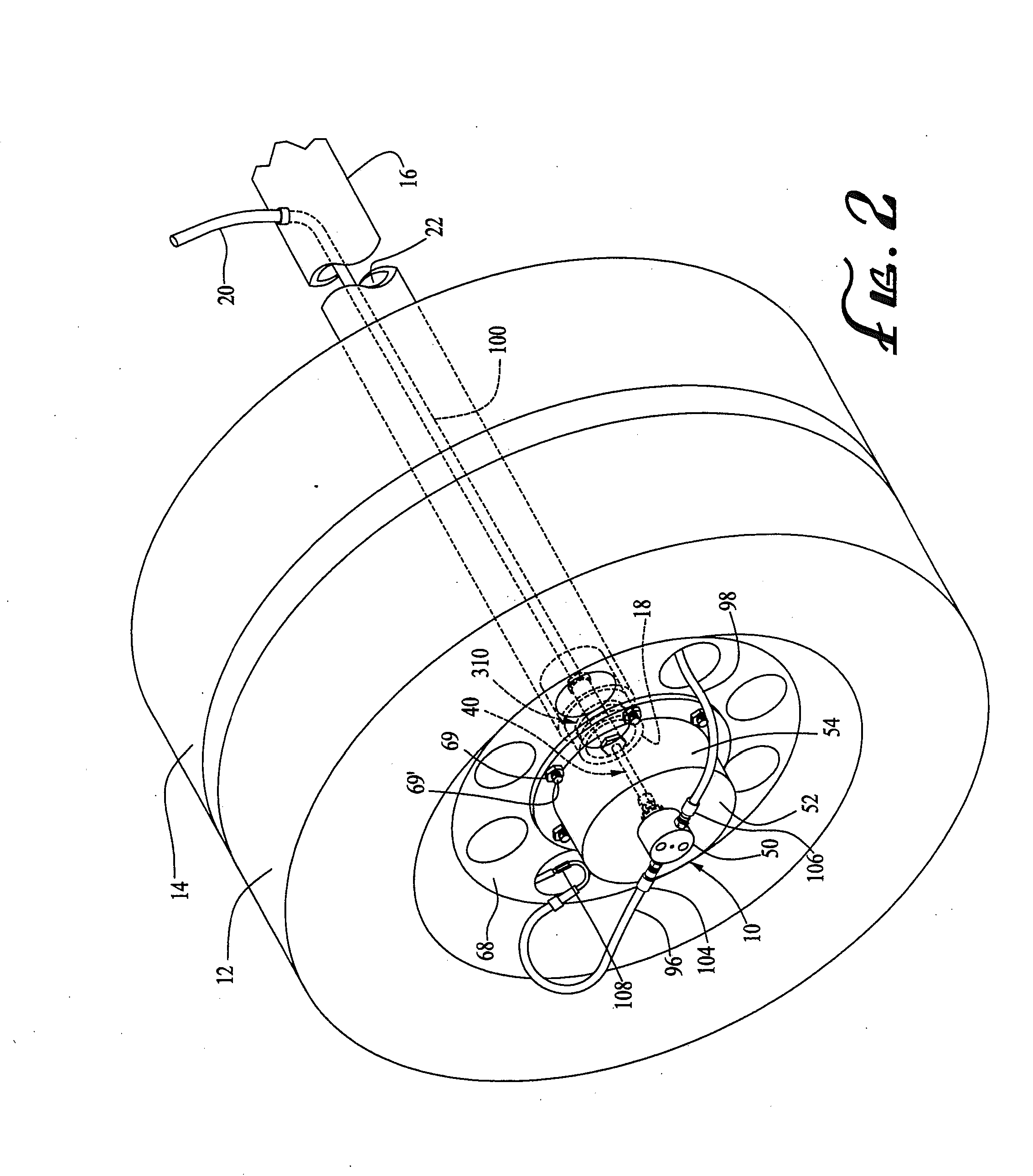
[0030]Referring now in detail to the drawings, the rotary union assembly 10 of the present invention, while useable on a wide variety of movable vehicles employing stationary axles for automatically maintaining the inflation pressure of the pneumatic tires thereon, is particularly adapted for use on tractor trailers. Accordingly, the assembly 10 will be described in conjunction with a pair of adjacent vehicle tires 12 and 14 mounted on a stationary tractor trailer, axle 16. While identical rotary union assemblies 10 are provided at the end of each axle on the trailer to maintain the inflation pressure of the tires carried thereby, reference will be made to only one such assembly and the pair of tires it services.

[0031]The trailer axle 16 which carries tires 12 and 14 can be sealed and functions as an air conduit to communicate the spindles 18 welded to the extended ends of a trailer axle 16 with an air supply line 20. Such an arrangement is referred to herein as a sealed or pressuri...


PUM


Abstract

A rotary union assembly for an automatic tire inflation system for maintaining the pressure in the tires on a tractor trailer or other vehicle having a source of pressurized air for communication with the tires. The assembly communicates the tires with the air source through the axle interior using a conduit having a rigid portion and a flexible portion that extends between a support in the axle spindle and a rotary union housing secured against the outside end surface of the hub cap so as to be outside the wheel lubrication compartment and rotatable with the hub cap. The two-component conduit allows for a durable seal with the support in the axle spindle and accommodates misalignment of the rotary union housing with the conduit support. Relief valves in the housing prevent excessive pressure buildups in the housing and in the hub cap in the event of an air leak.

Description

CROSS REFERENCE TO RELATED APPLICATIONS[0001]This is a continuation of pending application Ser. No. 11 / 051,314 filed Feb. 4, 2005, entitled Rotary Union Assembly For Use In Air Pressure Inflation Systems For Tractor Trailer Tires, which is a continuation-in-part of application Ser. No. 10 / 851,441 filed May 21, 2004, now U.S. Pat. No. 6,968,882 issued Nov. 29, 2005, which is a continuation of application Ser. No. 09 / 993,019 filed Nov. 13, 2001 (now abandoned), which is a continuation of application Ser. No. 09 / 522,623 filed Mar. 10, 2000, now U.S. Pat. No. 6,585,019 issued Jul. 1, 2003, which is a continuation of application Ser. No. 09 / 079,571 filed May 14, 1998, now U.S. Pat. No. 6,105,645 issued Aug. 22, 2000. This is also a continuation-in-part of application Ser. No. 10 / 941,774 filed Sep. 15, 2004, now U.S. Pat. No. 7,117,909 issued Oct. 10, 2006, entitled Expandable Spindle Plug Assembly For use With Automatic Tire Inflation Systems, which is a continuation-in-part of applicati...

Claims


Application Information

Patent Timeline
Patent Type & Authority Applications(United States)
IPC IPC(8): B60C23/00B60C29/06B60B27/02F16N99/00
CPCB60C23/003B60C23/00336B60C23/00363B60C23/00345B60C23/00318B60C23/00354
Inventor INGRAM, ANTHONY L.JONES, JOHNATHAN G.
Owner AIRGO IP
Why Eureka
Try Eureka