Image Display Device
a display device and image technology, applied in the direction of discharge tube luminescnet screen, discharge tube/lamp details, cathode ray tube/electron beam tube, etc., can solve the problems of display defect, electron source often destroyed, and electron source positioned on the outermost periphery of the display region
- Summary
- Abstract
- Description
- Claims
- Application Information
AI Technical Summary
Benefits of technology
Problems solved by technology
Method used
Image
Examples
embodiment 1
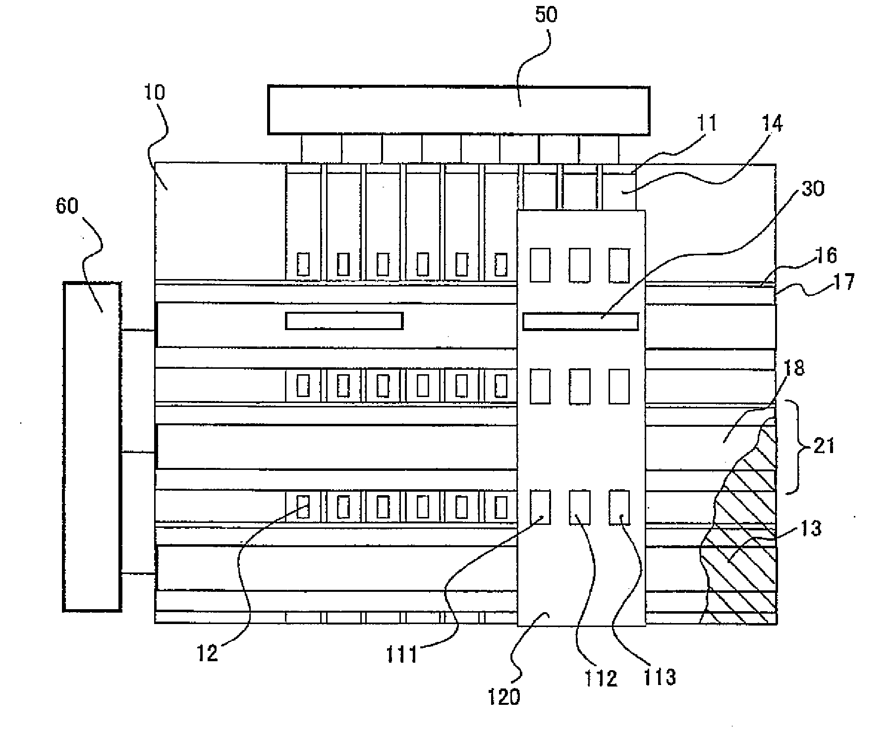
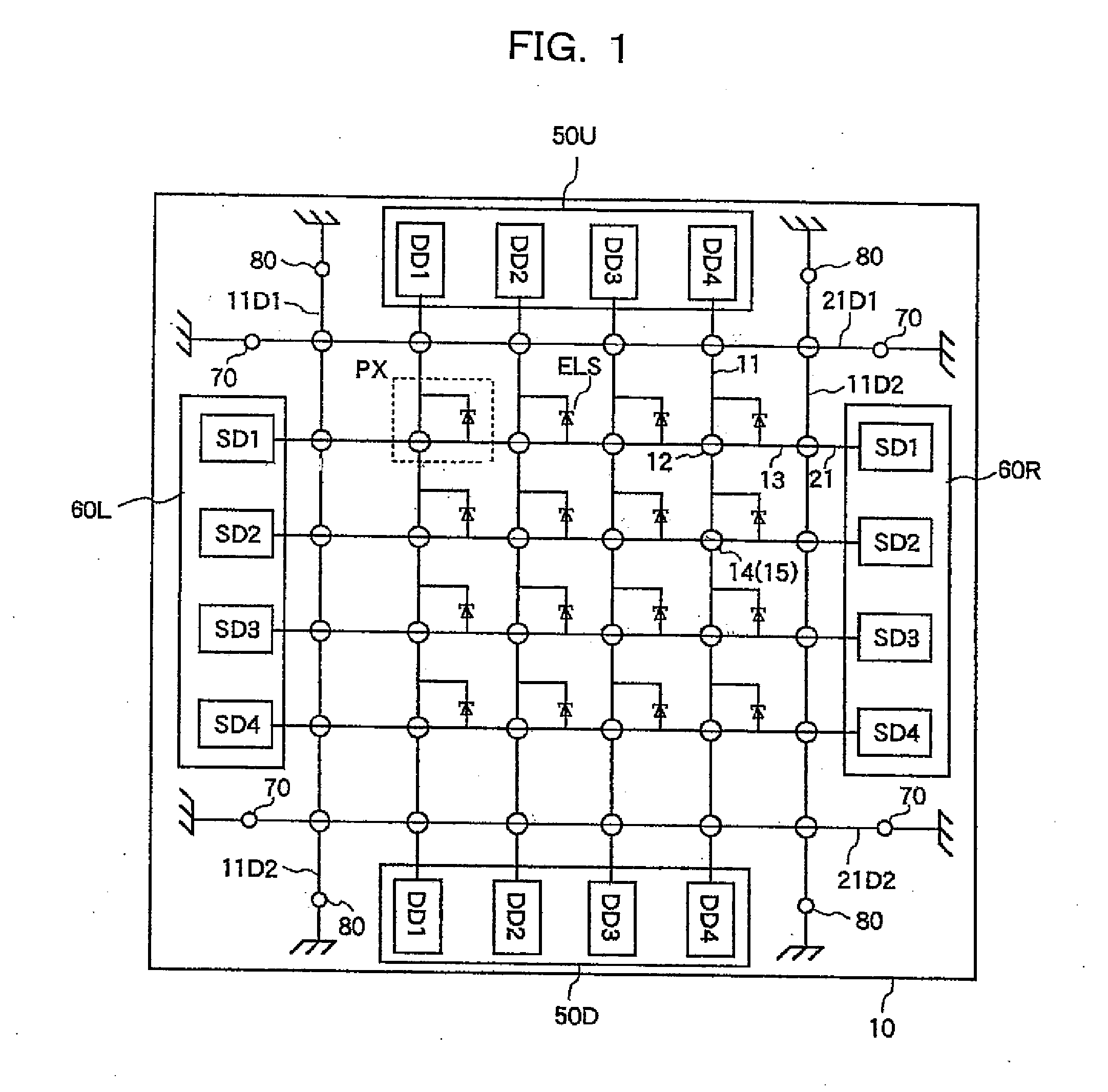
[0029]FIG. 1 is a schematical plan view of a cathode substrate to explain Embodiment 1 of an image display device according to the present invention. A bottom electrode 11, serving as data line, and a top electrode 13, to which electric current is supplied via a scan line (scan line bus) 21 in FIG. 1, are arranged (normally crossing perpendicularly to each other) on inner surface of a cathode substrate 10 preferably made of glass and positioned at an intersection via a field insulator 14 and an interlayer insulator 15. At the intersections, pixels PX comprising electron sources ELS are arranged in form of matrix.
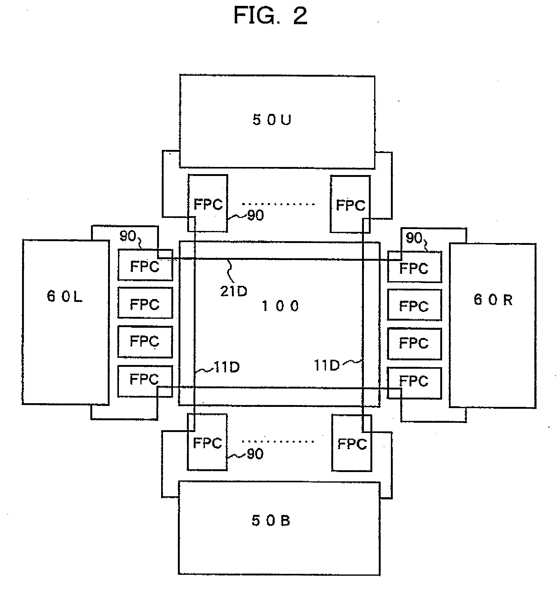
[0030]The bottom electrode 11, serving as data line, is directly provided above and below the cathode substrate 10 or it is driven by data line driving circuits 50U and 50D connected with a flexible printed board. The data line driving circuits 50U and 50D comprise data line driving circuit chips DD1, DD2, DD3, DD4, . . . corresponding respectively to the bottom electrode 11...
PUM
 Abstract
Description
Claims
Application Information
 - R&D
- Intellectual Property
- Life Sciences
- Materials
- Tech Scout
- Unparalleled Data Quality
- Higher Quality Content
- 60% Fewer Hallucinations
Browse by: Latest US Patents, China's latest patents, Technical Efficacy Thesaurus, Application Domain, Technology Topic, Popular Technical Reports.
© 2025 PatSnap. All rights reserved.Legal|Privacy policy|Modern Slavery Act Transparency Statement|Sitemap|About US| Contact US: help@patsnap.com


