
Backlit Display and Backlight System Thereof

a backlight system and backlight technology, applied in the field of backlight display, can solve problems such as not being desirable, and achieve the effect of reducing or preventing light emission interference, reducing or preventing interferen

Inactive Publication Date: 2008-08-07
HONG KONG APPLIED SCI & TECH RES INST
View PDF7 Cites 35 Cited by
  • Summary
  • Abstract
  • Description
  • Claims
  • Application Information

AI Technical Summary

Benefits of technology

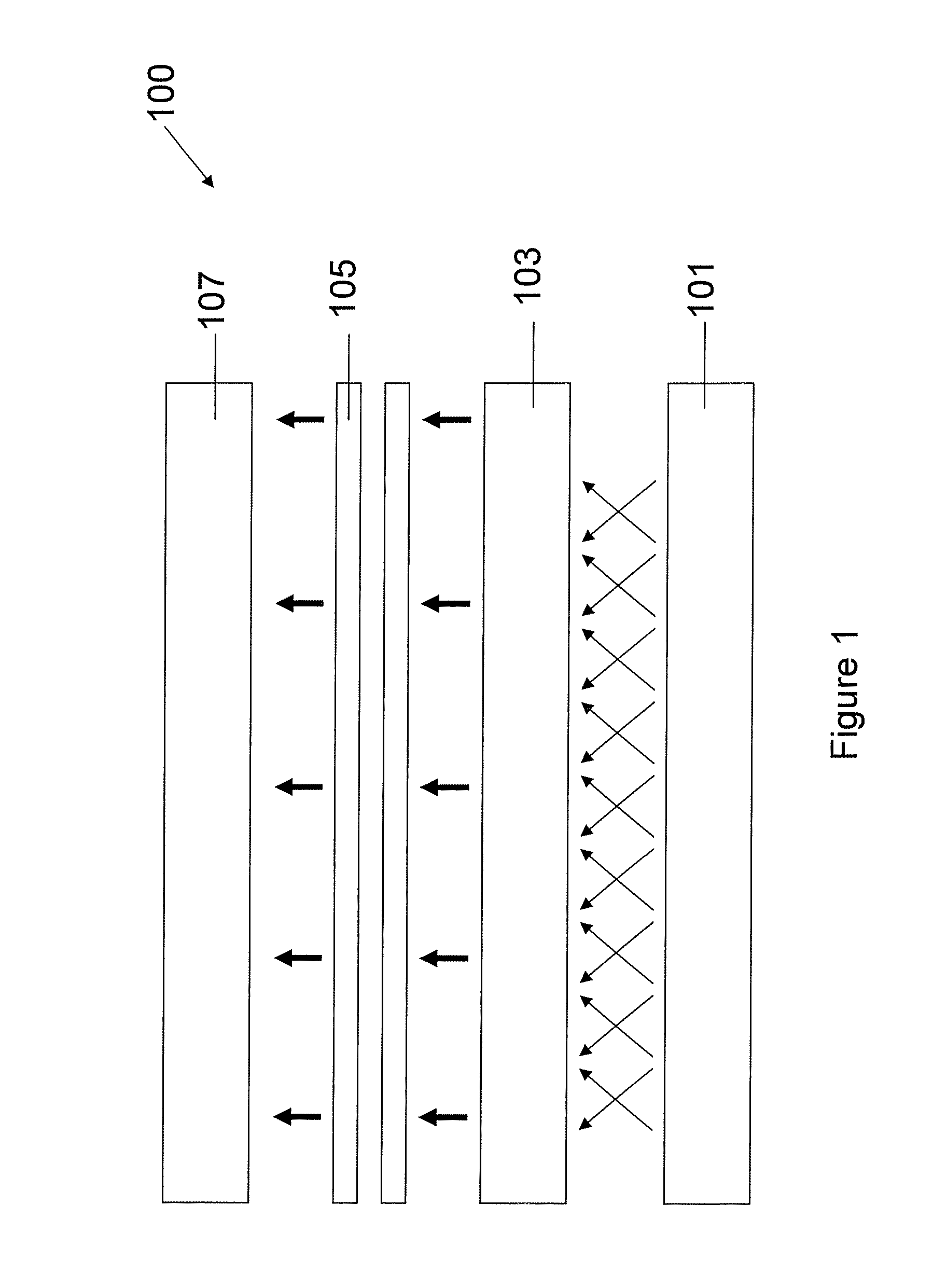
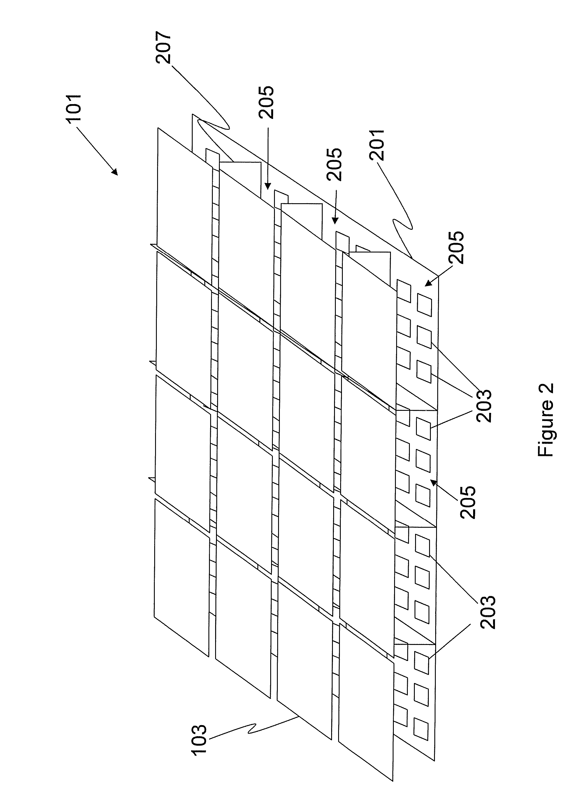
[0014]A plurality of optical insulators may be further located between the backlight units or located so as to define the backlight units, the optical insulator minimizing, reducing or preventing interference of light emission between adjacent backlight units. Each insulator may include at least one substantially reflective surface between adjacent backlight units.
[0015]Light guide plates may be provided having at least one reflective or totally internal reflective side surface so as to reduce or prevent interference between adjacent backlight units.
[0031]A plurality of optical insulators may be located between the backlight units or located so as to define the backlight units, the optical insulator minimizing, reducing or preventing interference of light emission between adjacent backlight units. Each insulator may include at least one substantially reflective surface between adjacent backlight units.
[0032]The light guide plates may be provided having at least one reflective or totally internal reflective side surface so as to reduce or prevent interference between adjacent backlight units.

Problems solved by technology

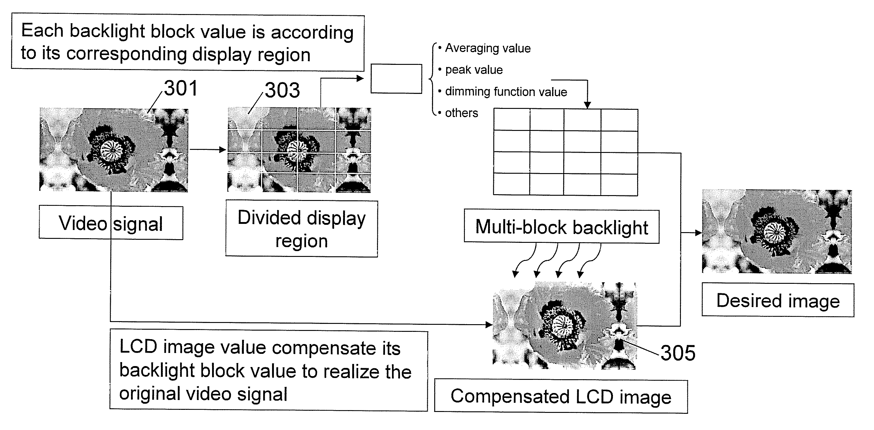
However, such a design may require a large volume of calculation to process the input image for the purpose of compensating the adjustment in the backlight, which may not be desirable.

Method used


Image

  • Backlit Display and Backlight System Thereof
  • Backlit Display and Backlight System Thereof
  • Backlit Display and Backlight System Thereof

Examples


second embodiment

[0067]FIG. 5 illustrates a backlight system 500, similar to the embodiment of FIG. 2, but with a plurality of cold cathode fluorescent lamps 501 (CCFL) on a CCFL backlight board 503 and grouped into a plurality of groups, instead of the LEDs.

third embodiment

[0068]FIG. 6 illustrates a backlight system 600, having a plurality of organic LED (OLED) films 601 on a backlight board 603, each OLED 601 functioning similar to a block of LEDs of the embodiment of FIG. 2. The backlight system 600 is in close proximity to the display (not shown in FIG. 6) to reduce or minimize interference between the light emission of different OCLE films 601.

fourth embodiment

[0069]FIG. 7 illustrates a backlight system 700, similar to the embodiment of FIG. 6, but having only one OLED film 701 on the backlight board 703. The OLED film 701 is virtually divided into multiple blocks 705, and each block is driven and adjusted individually.


PUM


Abstract

A backlight system for a backlit display, the system comprising a plurality of backlight units corresponding to an adjacent region of a backlit display, each unit having at least one light emission source; and a controller for individually controlling each backlight unit to vary at least one light characteristic of light emission from each backlight unit, wherein the at least one light characteristic is defined by determining at least one predefined parameter of light for each of a plurality of regions of an image to be displayed on a backlit display, the regions of the image corresponding to an adjacent backlight unit.

Description

FIELD OF THE INVENTION[0001]The present invention relates to a backlit display, more particularly to a display having a dynamically controlled backlight system.BACKGROUND OF THE INVENTION[0002]Typically, liquid crystal displays (LCD) and liquid crystal on silicon (LCOS) displays are illuminated by a backlight source as the liquid crystals disposed in the LCD panel do not emit light. Instead, the liquid crystals either pass or impede the passage of light such that images may be displayed. In a conventional design, the backlight is typically a white light having as constant an intensity as possible across the LCD panel to present a highly uniform image on the display.[0003]In recent developments, it has been realized that in order to achieve better image representation on the display, it is desirable to have different backlight when displaying different images. For example, bright backlight can better present vivid sky and buildings; whereas dimmed backlight can better present stars i...

Claims


Application Information

Patent Timeline
Patent Type & Authority Applications(United States)
IPC IPC(8): G09G3/36
CPCG09G3/3426G09G2320/0233G09G2360/16G09G2330/021G09G2320/0646
Inventor HUANG, DANDINGLIU, YINGCHEN, SHOU LUNGPENG, HUAJUNTSAI, CHEN-JUNG
Owner HONG KONG APPLIED SCI & TECH RES INST
Learn More