Display system for vehicle

a display system and vehicle technology, applied in the field of vehicle display systems, can solve the problems of difficult to equalize brightness, difficult to standardize each hud device according to multiple kinds of vehicles, and non-uniform image brightness, etc., and achieve the effect of high brightness, simple structure and standardization of display systems

Inactive Publication Date: 2008-08-07
YAZAKI CORP
View PDF2 Cites 6 Cited by
  • Summary
  • Abstract
  • Description
  • Claims
  • Application Information

AI Technical Summary

Benefits of technology

[0015]According to the present invention, even if the displayed light path going from the display system to the projection area is different depending on types of vehicle, a direction of a light ray can be changed simply by adjusting the direction adjusting member. Furthermore, the light ray controller controls a direction of light going from the backlight to the indicator. As a result, a visual angle area of the light can be set to a prescribed area, and high brightness can be kept. Thereby, it is not required to redesign and produce component parts of the backlight depending on types of vehicle. Also, display quality can be maintained, and the component parts of the backlight can be mounted on many different types of vehicles. Therefore, the display system can be standardized at simple structure.
[0016]According to the present invention, in addition to the above mentioned advantage, light from the backlight can be emitted to the indicator. Furthermore, a direction of light can be adjusted by the direction adjusting member. Therefore, a visual angle area of light emitted from the indicator can be set to a prescribed area.
[0017]According to the present invention, in addition to the above mentioned advantage, by using a Fresnel lens which can align a direction of a light ray with a displayed light path, the display system of the present invention is able to correspond to various vehicles more easily. Also, by adjusting parameters of the Fresnel lens (curvature, Korenich constant, polynomial aspheric surface coefficient, etc.), a visual angle area of the light ray can be set to a prescribed area. Thereby, a direction of the light ray can be adjusted accurately further

Problems solved by technology

But, when a light source is close to an indicator, brightness of an image becomes non-uniform.
As a result, it is difficult to equalize the brightness.
Furthermore, each HUD device according to multiple kinds of vehicle can not standardize because it is required to design each HUD device corresponding to each vehicle.

Method used


Image

  • Display system for vehicle
  • Display system for vehicle
  • Display system for vehicle

Examples


Embodiment Construction

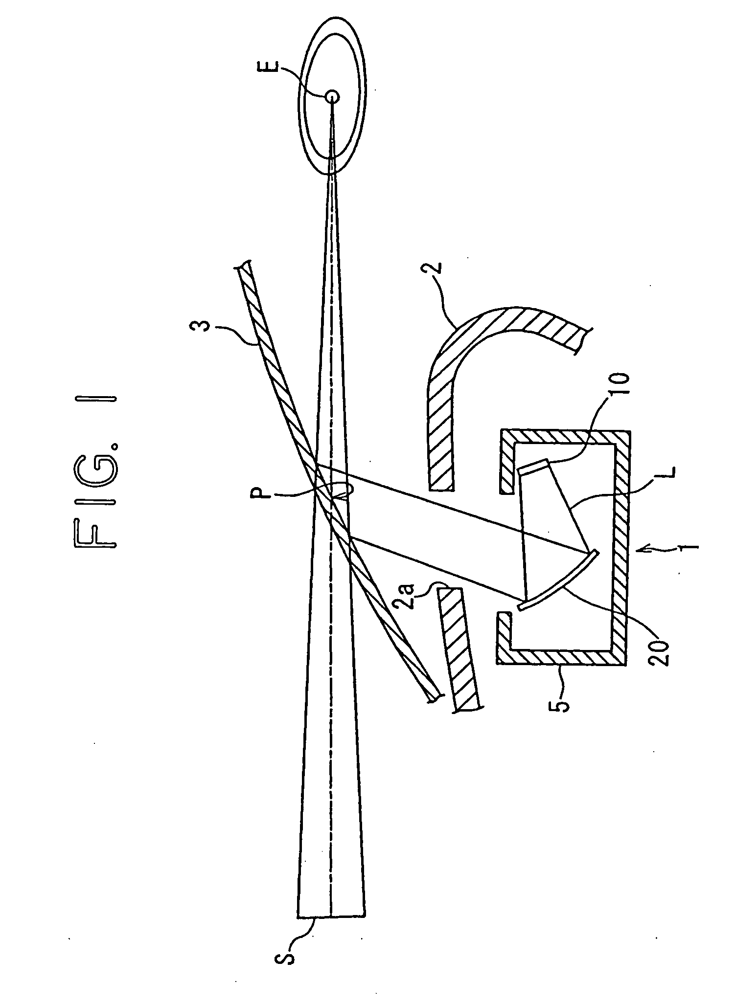
[0024]In the following, a display system for a vehicle according to a preferred embodiment of the present invention will be explained with reference to FIGS. 1-5.

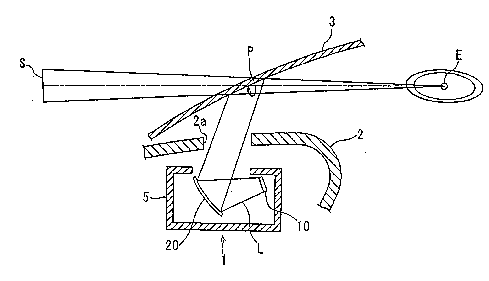
[0025]As shown in FIG. 1, a head-up display (HUD) device 1 is arranged in an instrument panel 2 of vehicle, and mounted on the vehicle. The HUD device 1 has a display system 10 for a vehicle of the present invention, and a reflecting member 20. The display system 10 and the reflecting member 20 are received in a receiving case 5. That is, the display system 10 is positioned in a predetermined place by the receiving case 5 of the vehicle.

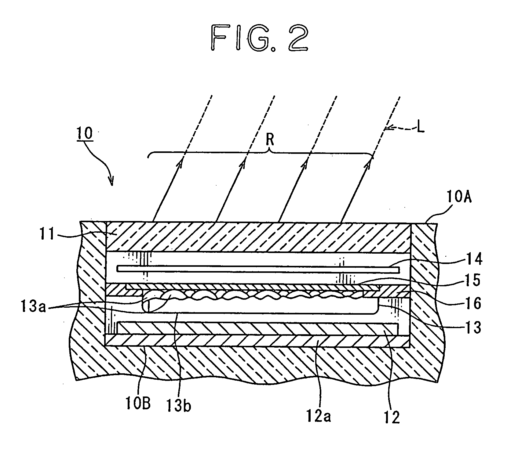
[0026]As shown in FIG. 2, the display system 10 has an indicator 11, a backlight 12, a lens array 13, a diffuser plate 14, a Fresnel lens 15 as a light ray controller and a direction adjusting member 16. These are mounted on housing 10A. In the display system 10, a virtual image S is superposed on a foreground of a vehicle. The virtual image S is given by projecting a light ray R from the ba...


PUM


Abstract

The present invention is to provide a display system for a vehicle. The display system is able to keep display quality and to be mounted on a vehicle of various types. A display system for a vehicle has an indicator, a backlight arranged on a back side of the indicator, a light ray controller and a direction adjusting member. The backlight emits a light passing through the indicator. The light ray controller is arranged between the indicator and the backlight, and controls a direction of light going from the backlight to the indicator. The direction adjusting member holds the light ray controller, and adjusts a direction of a light ray passed through the indicator.

Description

[0001]The priority application Number Japan Patent Application No. 2007-022717 upon which this patent application is based is hereby incorporated by reference.BACKGROUND OF THE INVENTION[0002]1. Filed of the Invention[0003]The present invention relates to a display system for a vehicle to be mounted on the vehicle, and a virtual image projected on a projection area of the vehicle, onto which area light outgoing from the backlight passed through the indicator is projected, and a front view of the vehicle to be seen from an eye point of the vehicle through the projection area are seen in a superimposed manner.[0004]2. Description of the Related Art[0005]Recently, with increase and diversification of information required by a driver during a drive, a projection-type display unit called a head-up display (HUD) device has been adopted so that information, which cannot be displayed in a meter unit due to the lack of the space, is displayed on a windshield as a virtual image, thereby a dri...

Claims


Application Information

Patent Timeline
Patent Type & Authority Applications(United States)
IPC IPC(8): G02B27/01
CPCG02B3/08G02B2027/0118G02B27/0101G02B5/02
Inventor MATSUSHITA, JUNICHI
Owner YAZAKI CORP
Why Eureka
Try Eureka