Method and Apparatus for Pulse Optimization for Hardware Implementation

a pulse optimization and hardware technology, applied in the field of communication systems, can solve the problems of increasing the amount of information of wireless service providers, unable to be altered without violating the standard's specifications, and becoming even more difficult, so as to avoid excessive out-of-channel power generation, minimize error functions, and increase the level of in-channel distortion of communications signals

Inactive Publication Date: 2008-08-07
PANASONIC CORP
View PDF5 Cites 30 Cited by
  • Summary
  • Abstract
  • Description
  • Claims
  • Application Information

AI Technical Summary

Benefits of technology

[0015]According to one exemplary embodiment, a first finite length constraint is identified and a second out-of-band power criterion is identified. An error function is then defined which measures the distortion of the generated signal relative to an ideal reference pulse. The error function is minimized to determine optimized pulses, which when used to pulse-shape a modulated communications signal, do not substantially contribute to an increased level of in-channel distortion of the communications signal. To avoid the generation of excessive out-of-channel power, minimization may also be performed subject to a predetermined maximum allowable out-of-channel power condition.

Problems solved by technology

Because it is a highly regulated and limited resource, however, wireless service providers are faced with the challenge of increasing the amount of information that can be transmitted in given portions of the spectrum.
This challenge of increasing what is often referred to as “spectral efficiency” is a difficult endeavor, which has become even more difficult in recent years due to the exploding demand for wireless communications services.
Although increasing the modulation complexity can help to increase spectral efficiency, modulation schemes are typically specified and fixed by standards and, therefore, cannot be altered without violating the standard's specifications.
Because the spectral roll-off is gradual, the two channels overlap and interfere with each other, even though a guard band is employed to lessen the effects of the interference.
Unlike the modulation scheme, the pulse-shaping filter is not typically fixed by wireless standards.
Unfortunately, from an implementation perspective, designing a filter having an infinite time impulse response is not practical.
Unfortunately, this windowing process does not provide any means for preserving the modulation accuracy of the signal generated by the modulator and, therefore, does not account for distortion being introduced into the signal.
Distortion can hinder the ability of the transmitter to generate signals that can be reliably detected at the receiving end of the communications system.

Method used


Image

  • Method and Apparatus for Pulse Optimization for Hardware Implementation
  • Method and Apparatus for Pulse Optimization for Hardware Implementation
  • Method and Apparatus for Pulse Optimization for Hardware Implementation

Examples


Embodiment Construction

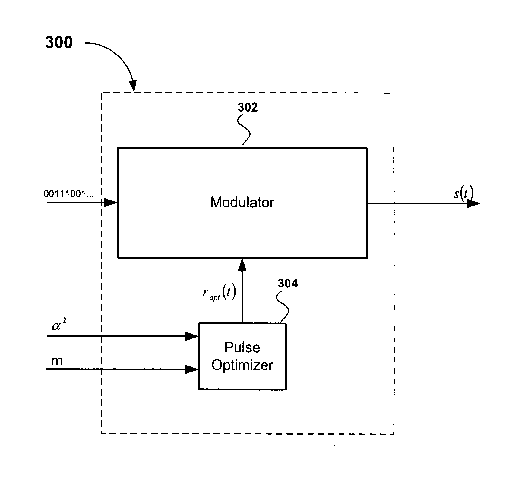
[0028]Referring first to FIG. 3, there is shown a block diagram of a pulse optimizing modulator apparatus 300, according to an embodiment of the present invention. The pulse optimizing modulator apparatus 300 comprises a modulator 302 and a pulse optimizer 304. The modulator 302 is configured to receive a digital message and generate a signal s(t), which is subsequently frequency up-converted and radiated by an antenna. As explained in detail below, the pulse optimizer 304 is configured to receive energy parameters α2 characterizing a predetermined adjacent channel leakage ratio (ACLR) and a finite pulse-length parameter m to compute an optimized pulse ropt(t) The optimized pulse ropt(t) is used by a pulse-shaping filter of the modulator 302 to generate the signal s(t).

[0029]FIG. 4 is a block diagram illustrating how the optimized pulse ropt(t) generated by the pulse optimizer 304 in FIG. 3 can be used in a communications transmitter 400, according to an embodiment of the present in...


PUM


Abstract

Methods and apparatus for optimizing pulses provided by a pulse-shaping filter implemented in hardware. Pulses are optimized and generated by the pulse-shaping filter that are of finite length and meet one or more signal quality criteria, e.g., error vector magnitude (EVM) and / or adjacent channel leakage ratio (ACLR). According to one exemplary embodiment, a first finite length constraint is identified and a second out-of-band power criterion is identified. An error function is defined which measures the distortion of the generated signal relative to a reference pulse modeled after an ‘ideal’ pulse. The error function is minimized to determine optimized pulses, which when used to pulse-shape a communications signal, do not substantially increase in-channel distortion of said communications signal. To avoid the generation of excessive out-of-channel power, minimization is performed subject to a predetermined maximum allowable out-of-channel power condition.

Description

CROSS-REFERENCE TO RELATED APPLICATIONS[0001]This patent application claims the benefit of U.S. Provisional Patent Application No. 60 / 899,954, filed on Feb. 7, 2007, the disclosure of which is hereby incorporated by reference.FIELD OF THE INVENTION[0002]The present invention relates in general to communications systems. More specifically, the present invention relates to the conditioning of baseband modulated signals.BACKGROUND OF THE INVENTION[0003]The radio spectrum is that part of the electromagnetic spectrum which is used by essentially all of today's telecommunications services. Because it is a highly regulated and limited resource, however, wireless service providers are faced with the challenge of increasing the amount of information that can be transmitted in given portions of the spectrum. This challenge of increasing what is often referred to as “spectral efficiency” is a difficult endeavor, which has become even more difficult in recent years due to the exploding demand f...

Claims


Application Information

Patent Timeline
Patent Type & Authority Applications(United States)
IPC IPC(8): H04L25/03
CPCH04L25/03834
Inventor SCHELL, STEPHAN V.LIANG, PAUL CHENG-PO
Owner PANASONIC CORP
Why Eureka
Try Eureka