
Flexible optical fiber tape and distribution cable assembly using same

a technology of optical fiber tape and distribution cable, which is applied in the direction of optics, fibre mechanical structures, instruments, etc., can solve the problems of unsuitable indoor applications and environments of cables, and achieve the effect of reducing the degree of bending of optical fiber and easy separation of one or more substrates

Inactive Publication Date: 2008-08-07
CORNING CABLE SYST LLC
View PDF15 Cites 98 Cited by
  • Summary
  • Abstract
  • Description
  • Claims
  • Application Information

AI Technical Summary

Benefits of technology

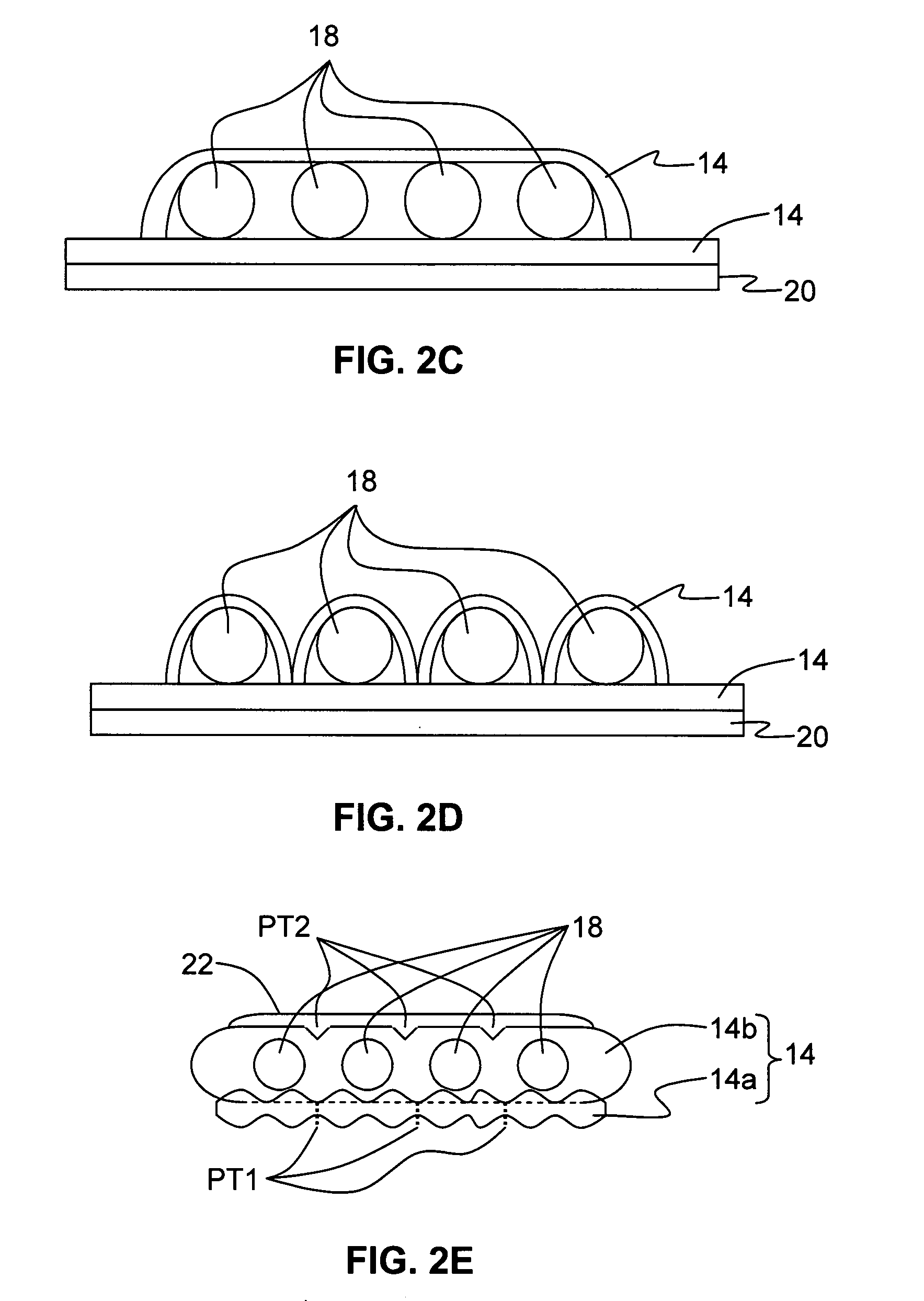
[0006]In various embodiments, the present invention provides a flexible, optical-fiber-based tape particularly suited for but not limited to indoor applications wherein the optical fiber need not or cannot be hidden from view in a building's infrastructure. The tape may optionally include a fire-retardant substrate in the form of a strip having a central longitudinal axis and opposing upper and lower surfaces. At least one optical fiber is maintained by the substrate, e.g., either between the upper and lower surfaces, or attached to the upper or lower surface. The optical fiber can run substantially parallel to the central longitudinal axis, or can follow a curved path having curved sections for reducing the degree of bending of the optical fiber when the tape is bent. The tape may also include one or more adhesive layers formed respectively on one or both of the upper and lower surfaces (i.e., the outer surfaces). The adhesive layer is used for adhering the tape to an exterior surface, such as a floor, wall or ceiling. Where the tape has a plurality of optical fibers the spacing among one or more optical fibers is optionally such that easy separation of one or more substrates is possible to separate one or more optical fibers from the tape.

Problems solved by technology

While there has been an increase in the development of outdoor distribution cables that satisfy outdoor installation and environmental requirements, such cables are not suitable for indoor applications and environments, such as multi-dwelling unit (MDU) applications for FTTH (“Fiber-to-the-home) networks.

Method used


Image

  • Flexible optical fiber tape and distribution cable assembly using same
  • Flexible optical fiber tape and distribution cable assembly using same
  • Flexible optical fiber tape and distribution cable assembly using same

Examples


Embodiment Construction

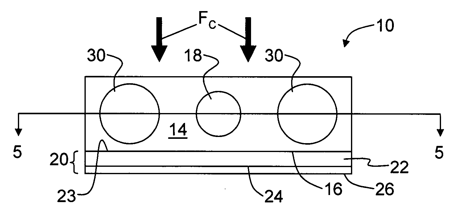
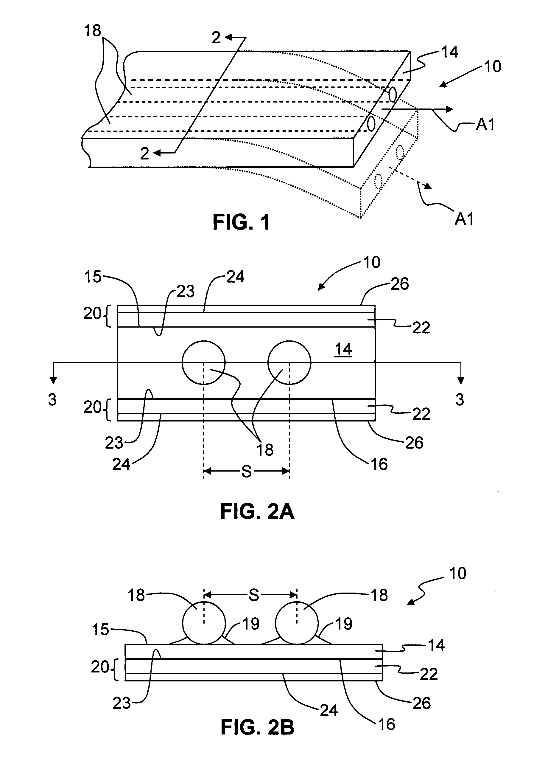
[0029]The present invention provides various embodiments of an optical fiber tape assembly for both indoor and outdoor applications. FIG. 1 is a perspective view of a portion of a generalized optical-fiber-based tape apparatus (“tape”) 10, illustrating the tape's flexibility as depicted by the dotted lines. Tape 10 has a longitudinal axis A1 that runs down the center of the tape in the longitudinal direction and includes at least one optical fiber 18 that runs along a length of a substrate 14. Tape 10 is shown as having an end with a generally rectangular cross-section, but other shapes are possible. Generally speaking, the cross-section of tape 10 has a height that is smaller than its width. Moreover, depending on its construction such as optical fiber count, materials, and the like, tape 10 can be relatively narrow or up to several centimeters wide.

[0030]FIG. 2A is a cross-sectional view of the explanatory embodiment of tape 10 taken along the line 2-2 of FIG. 1. Tape 10 of FIG. 2...


PUM


Abstract

A flexible optical fiber tape is formed from a substrate in the form of a strip adapted to maintain at least one optical fiber. The substrate may include an adhesive layer on at least one side for securing the tape to an external surface such as an interior floor, wall or ceiling. The tape may also have a flame-retardant characteristic. The optical fiber can run substantially longitudinally along the substrate, or can have one or more curved sections that allow for bending the tape without a substantially bending the at least one optical fiber. The tape may also include one or more network access points (NAPs) adapted to allow for optical communication between at least one external optical fiber and the at least one optical fiber maintained by the substrate. A distribution cable based on the optical-fiber-based tape is also described.

Description

RELATED APPLICATIONS[0001]The present application claims priority to the provisional application filed on Feb. 2, 2007 and titled on the front page “Flexible Optical Fiber Tape and Distribution Cable Assembly Using Same” and having the inventive entity of Reginald Roberts and Jorge Roberto Serrano.BACKGROUND OF THE INVENTION[0002]1. Field of the Invention[0003]The present invention relates generally to optical fibers and optical fiber cables, and in particular to a flexible optical fiber tape having robust material properties and features that make it suitable for both indoor and outdoor use, and a distribution cable assembly based on the flexible optical fiber tape.[0004]2. Technical Background[0005]Optical fiber is increasingly being used for a variety of broadband communications including voice, video and data transmissions. As a result of the increasing demand for broadband communications, fiber optic networks typically include distribution cables having network access points (N...

Claims


Application Information

Patent Timeline
IPC IPC(8): G02B6/44
CPCG02B6/02333G02B6/4475G02B6/4404G02B6/3608G02B6/475
Inventor ROBERTS, REGINALDSERRANO, JORGE ROBERTOSUMMERS, TIMOTHY FREDERICK
Owner CORNING CABLE SYST LLC
Learn More