Photoirradiation device and fiber rod

a technology which is applied in the field of photoirradiation device and fiber rod, can solve the problems of low light utilization efficiency, reduced light utilization efficiency, and high positioning accuracy, and achieve the effect of low damping factor

Active Publication Date: 2006-09-05
GC CORP
View PDF7 Cites 21 Cited by
  • Summary
  • Abstract
  • Description
  • Claims
  • Application Information

AI Technical Summary

Benefits of technology

[0025]According to the invention, the light beams emitted from the plurality of point light so

Problems solved by technology

However, in the photoirradiation device in which individual light-emitting diode and the irradiation opening are connected through the optical fiber, when a distance between an end face of the optical fiber and the light-emitting diode becomes longer, there was a problem that utilization efficiency of the light is decreased and high accuracy is required for positioning.
In the photoirradiation device in which the irradiation light beam emitted from each light-emitting diode is guided to the incident port of the photoirradiation head through one condenser lens, there was the problem that it is difficult to focus the irradiation light beam of the light-emitting diode arranged at a position which is far away from an optical axis and the utilization effic

Method used


Image

  • Photoirradiation device and fiber rod
  • Photoirradiation device and fiber rod
  • Photoirradiation device and fiber rod

Examples


Embodiment Construction

[0034](First Invention)

[0035]An embodiment of the first invention will be described below referring to the accompanying drawings. In the embodiment, the dental photoirradiation device for curing the photo-polymerization resin will be described as an example of the photoirradiation device.

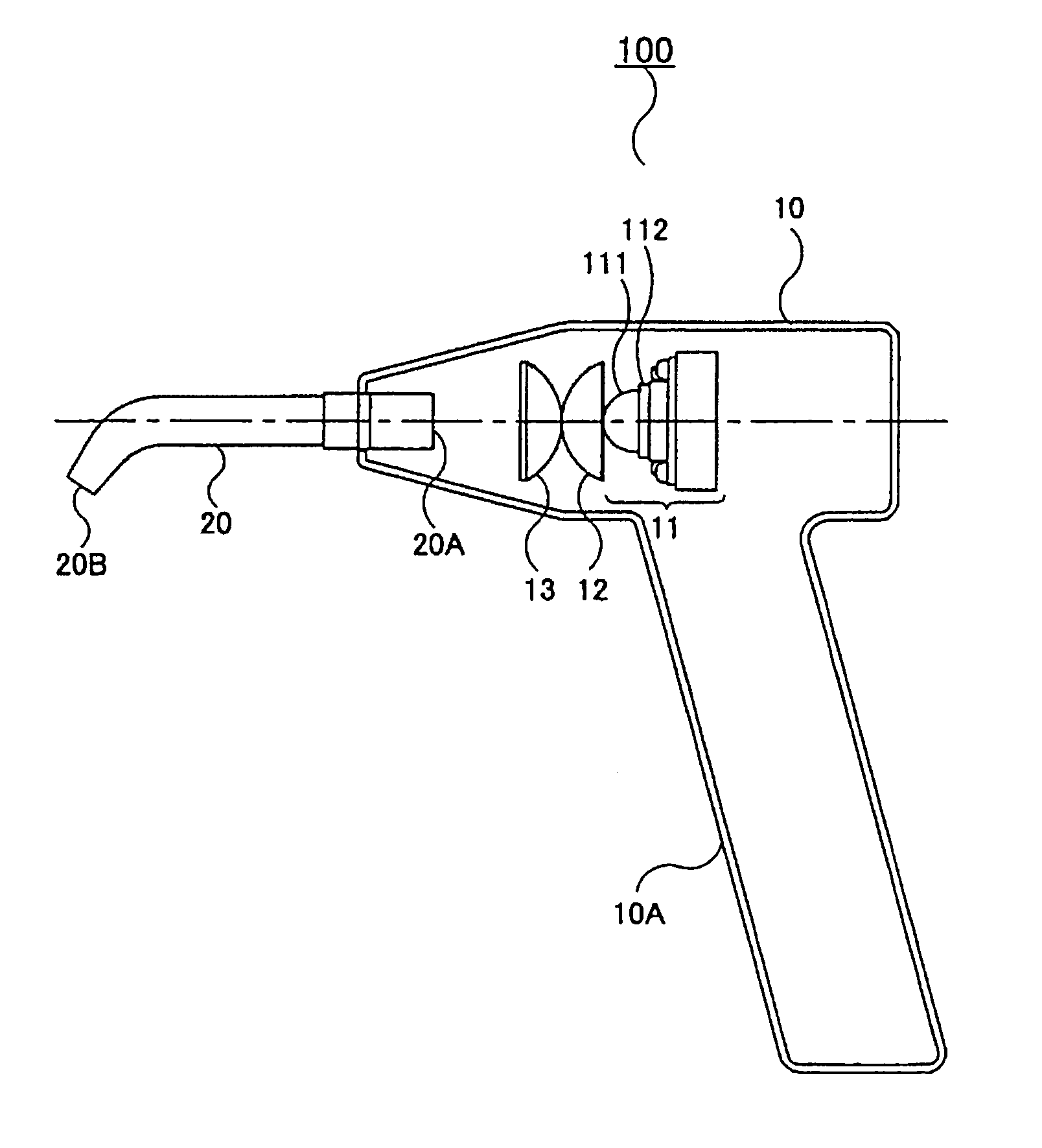
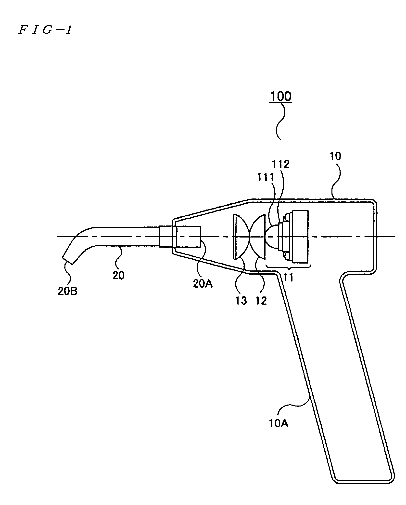
[0036]FIG. 1 is a sectional view showing a configuration of the dental photoirradiation device according to the embodiment. A dental photoirradiation device 100 includes a main body 10 and a lightguide 20 which is provided on an end of the main body 10. The main body 10 has a cannonball shape, a pencil shape, or the like. Sometimes a grip 10A is provided in the main body as shown in FIG. 1. A control switch or the like (not shown) is provided in the main body 10 or the grip 10A, so that a dentist can operate to turn on and off the irradiation while holding the main body 10 or the grip 10A.

[0037]The main body 10 incorporates an LED light-emitting unit 11, a second lens 12, and a third lens 13. The LE...


PUM


Abstract

A photoirradiation device in which an optical system can be miniaturized and utilization efficiency of light can be improved in a manner that includes a first lens and a second lens, which share refraction of light to convert light beams emitted from a plurality of light sources into the light beams substantially parallel to an optical axis, and a third lens focusing the light beams from the second lens on an incident surface 20A of a lightguide 20. A fiber rod which can output uniform light beams in a manner that includes a first rod having a single fiber and a second rod having a plurality of fibers.

Description

FIELD OF THE INVENTION[0001]The present invention relates to a photoirradiation device which focuses light beams emitted from a plurality of point light sources to irradiate. Further, the invention relates to a fiber rod and the photoirradiation device which uses the fiber rod.DESCRIPTION OF THE RELATED ART[0002]A photo-polymerization resin becomes widespread as a dental material for restoration of tooth in dentistry. The photo-polymerization resin is filled into a cavity of a tooth of a patient, and then the photo-polymerization resin is cured by being irradiated with light from the photoirradiation device. The photoirradiation devices including a plurality of light-emitting diodes as well as the photoirradiation devices in which a halogen lamp or a xenon lamp is used as the light source are well known.[0003]In Japanese Patent No. 2979522 (FIGS. 1 to 3), there is disclosed a device which includes the plurality of light-emitting diodes and focuses the light beams emitted from the li...

Claims


Application Information

Patent Timeline
IPC IPC(8): A61B1/07A61B1/06A61C13/15A61N5/06F21V8/00G02B6/04G02B27/00
CPCA61C19/004G02B6/0006G02B13/143G02B6/0008A61N2005/0652Y10S362/804G02B6/04Y10S362/80
Inventor TAKADA, MITSUAKIKOBAYASHI, AIICHIOMORI, SHINYAOHNO, MASAFUMI
Owner GC CORP
Why Eureka
Try Eureka