High-speed gate driver for power switches with reduced voltage ringing

a gate driver and power switch technology, applied in electronic switching, electrical equipment, pulse generators, etc., can solve the problems of non-recoverable damages and premature aging, and achieve the effect of reducing noise and attenuating premature aging issues

Inactive Publication Date: 2014-04-17
SL3J SYST S A R L
View PDF4 Cites 29 Cited by
  • Summary
  • Abstract
  • Description
  • Claims
  • Application Information

AI Technical Summary

Benefits of technology

[0019]This invention consists of a new method that exploits the characteristics of the gate driver circuit to cancel or to damp the high frequency ringing effect that takes place at power switch terminals when driven between ON and OFF states

Problems solved by technology

Although most techniques relative to gate drivers and power switch drivers seem to be in public domain today, the effect exploited in this patent does not seem to be previously known or employed in Integrated Circuit designs, and professionals employ empiric approaches to mitigate over-voltages stress due to energy ringing the parasitic reactive ele

Method used


Image

  • High-speed gate driver for power switches with reduced voltage ringing
  • High-speed gate driver for power switches with reduced voltage ringing
  • High-speed gate driver for power switches with reduced voltage ringing

Examples


Embodiment Construction

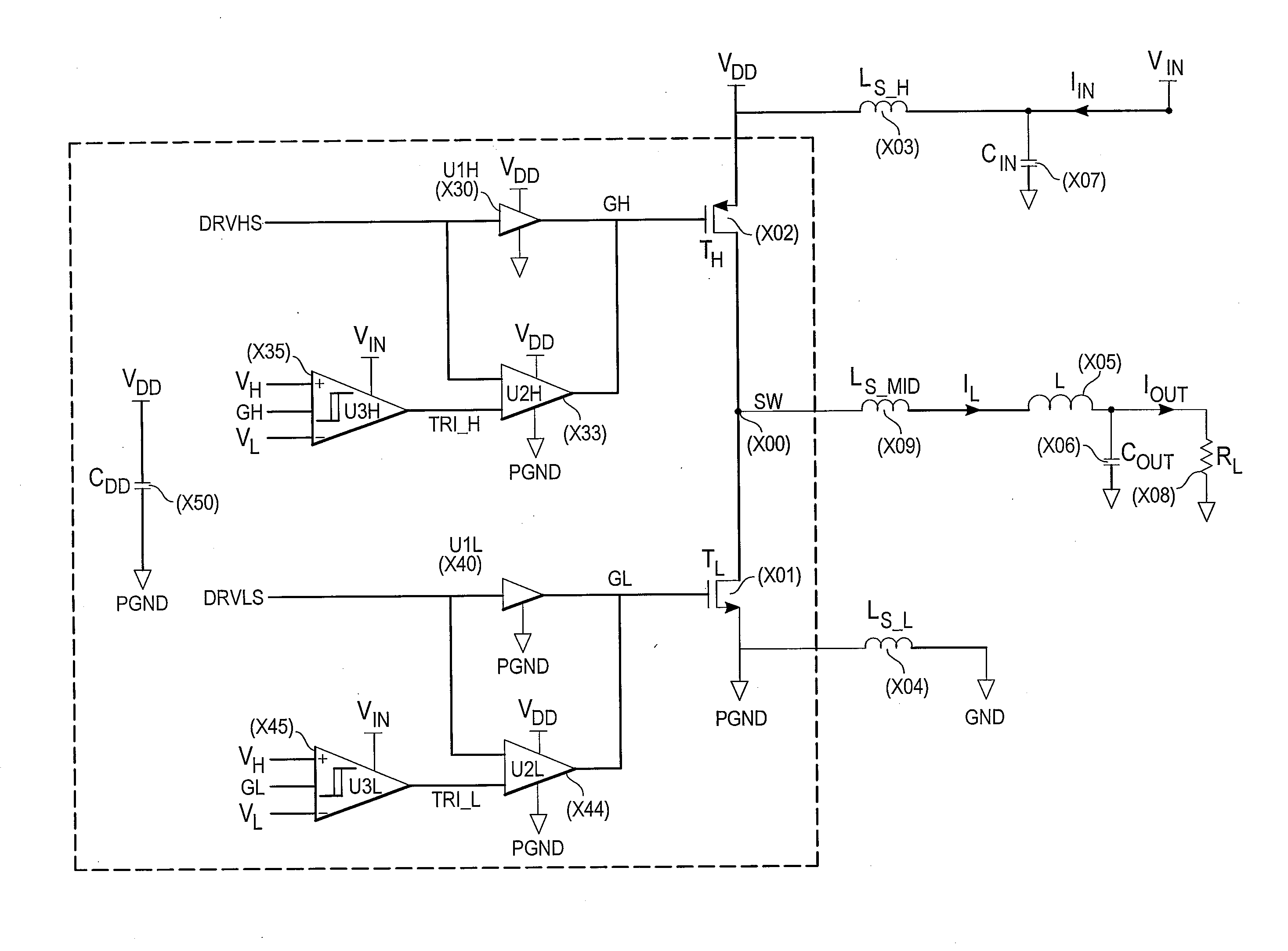
[0040]The high speed gate driver in accord with the present invention employs a method for reducing voltage ringing in high-speed power switches that are subject to very high di / dt. In particular, this invention proposes a modification of the gate driver circuit in order to allow, firstly, ultra-fast charge and discharge times of the gate charge and secondly to efficiently damp the parasitic stored energy.

[0041]The new gate driver circuit works as follows (see FIG. 7):[0042]Two parallel gate drive circuits, a weak drive section and a strong drive section are simultaneously activated in order to discharge the gate capacitance of the power switch in order to turn it off. It quickly reduces the conduction drain to source current to zero.[0043]A fast voltage sensor is used to detect when the gate control voltage effectively drops to zero.[0044]As soon as the gate control voltage drops to zero, the strong drive section is disabled. The weak driver section, still active, will maintain the...


PUM


Abstract

A fast power switch comprises one or more field-effect transistors, such as pull-up and pull-down transistors, that are coupled to a load. Respective driver electronic circuits for each of the field-effect transistors include parallel first and second drivers with a shared driver output coupled to a gate of the field-effect transistor. The first and second drivers are operative to switch the shared driver output for the appropriate field-effect transistor in response to a transition (e.g., low-to-high or high-to-low) at a driver input terminal. A control circuit enables the stronger second driver in response to a transition at the driver input terminal and subsequently disables the second driver once a transition threshold at the gate of the field-effect transistor(s) is crossed. The weaker first driver is sized to damp reactive energy at the load to minimize ringing.

Description

TECHNICAL FIELD[0001]The present invention relates to electronic power switches with modifications to the gate drivers for (1) accelerating switching and (2) eliminating or reducing voltage oscillations or ringing.BACKGROUND ART[0002]The input driver of a power switch, such as the gate driver of a power-MOSFET (TH or TL in FIG. 1), is usually designed to handle source and sink currents able to charge and discharge the gate capacitance in a very short duration. A series resistor RGL is usually added between the driver and the gate which is assumed to attenuate or prevent gate oscillations mainly when the device turns-on [Laszlo Balogh, “Design and Application Guide for High Speed MOSFET Gate Drive Circuits”, Triode Seminar SEM1400 (2001)]. A Schottky diode is usually added in parallel with the gate resistor in order to increase the sourced current and insure a sharp turn-on transition. Some designers recommend adding a few nano-Henry series inductance LGL between the driver and the g...

Claims


Application Information

Patent Timeline
IPC IPC(8): H03K3/00
CPCH03K17/082H03K19/00361H03K19/018507H03K2217/0063H03K2217/0072
Inventor AJRAM, SAMI
Owner SL3J SYST S A R L
Why Eureka
Try Eureka