Rigidity-Controllable Device and Damping-Controllable Shock-Absorbing Apparatus Comprising the Same

a technology of rigidity control and damping control, which is applied in the direction of shock absorbers, vibration dampers, material nanotechnology, etc., can solve the problems of damage to the material of the building or the bridge pier, the damage of the building or the bridge, and the inability to eliminate the shock caused by the working of the aircraft such as artificial satellites and photovoltaic devices. , to achieve the effect of high conductivity of nano-conductive materials and reduced power requirements

Inactive Publication Date: 2013-06-20
NATIONAL TSING HUA UNIVERSITY
View PDF5 Cites 0 Cited by
  • Summary
  • Abstract
  • Description
  • Claims
  • Application Information

AI Technical Summary

Benefits of technology

[0019]In the rigidity-controllable device of the present invention, preferably, the nano-conductive material has conductivity (σ) of 0.5×10⁻¹ S/m-8×10−1 S/m. More preferably, the condu...

Problems solved by technology

In the condition without any external force (for example, outer space), the shocks caused by the working of aircrafts such as artificial satellites and photovoltaic devices can only be eliminated by the materials contained therein, and there are no other external material can provide damping effect to the aircrafts to reduce these shocks.
When large amplitude vibrations are occurred on the building or the bridge piers torqued or vibration times are too long, the material of the building ...

Method used


Image

  • Rigidity-Controllable Device and Damping-Controllable Shock-Absorbing Apparatus Comprising the Same
  • Rigidity-Controllable Device and Damping-Controllable Shock-Absorbing Apparatus Comprising the Same
  • Rigidity-Controllable Device and Damping-Controllable Shock-Absorbing Apparatus Comprising the Same

Examples


embodiment 3

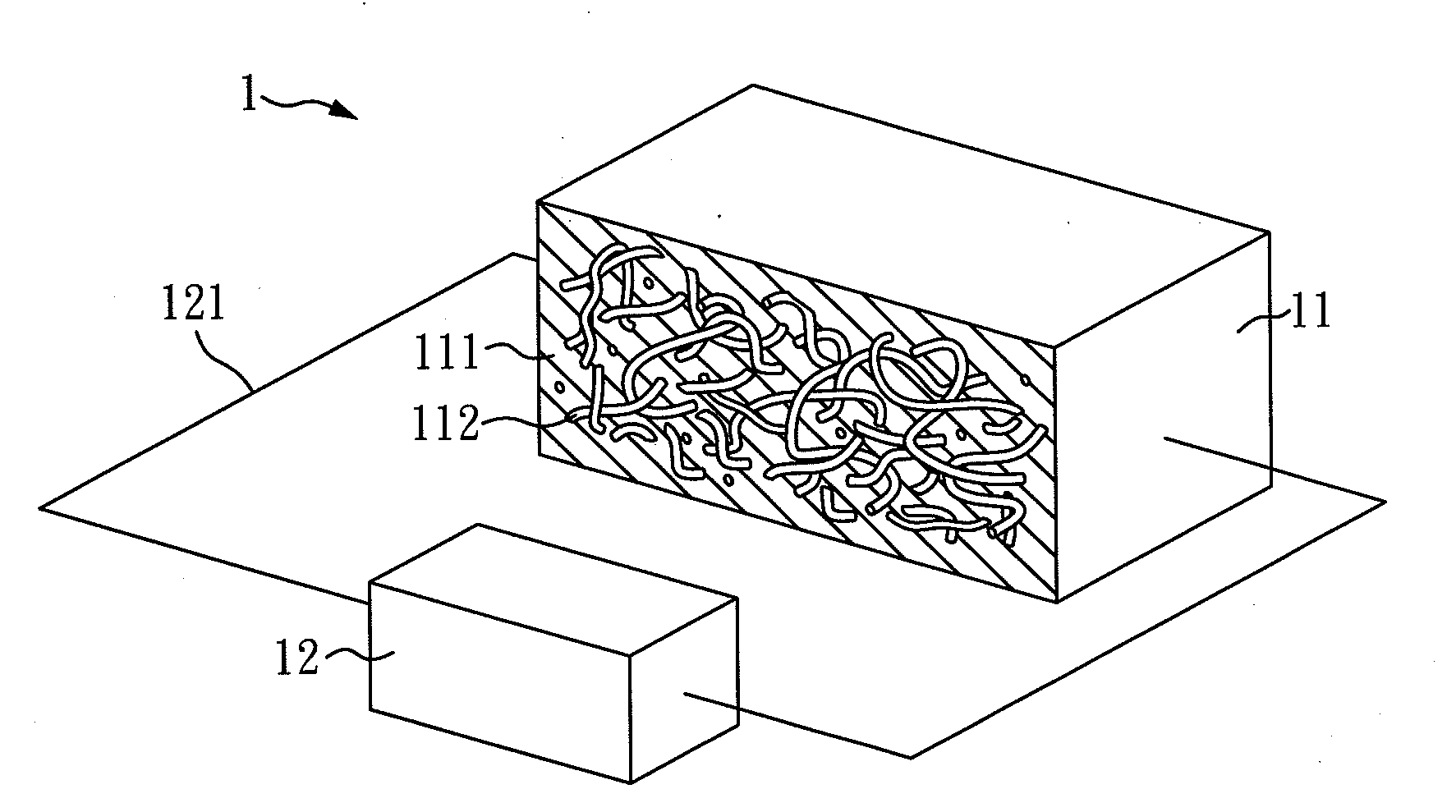
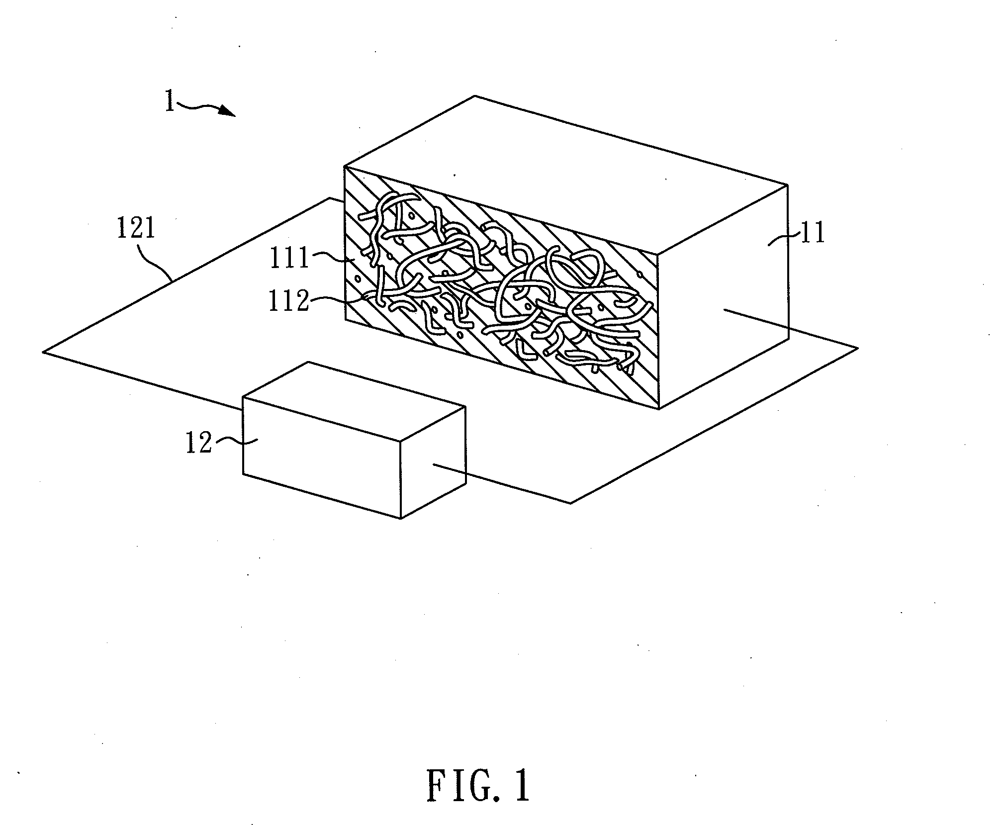
[0040]As shown in FIG. 1, the composite 11 (i.e. specimen) of Embodiment 2 was electrically connected to a power supply 12 to obtain a rigidity-controllable device 1 of the present embodiment.

[0041]The rigidity-controllable device 1 of the present embodiment comprises: a composite 11 comprising a polymer base 111, and a nano-conductive material 112 dispersed in the polymer base 111; and a power supply 12 electrically connecting with the composite 11 through an electric wire 121, and supplying electricity to the composite 11, wherein when the power supply 12 supplies the electricity to the composite 11, a temperature of the composite 11 is increased and thus the rigidity of the composite 11 is changed.

[0042]In the present embodiment, the material of the polymer base 111 is epoxy resin, and the nano-conductive material 112 is carbon nanotubes such as MWNT.

[0043]However, the nano-conductive material 112 is not limited to carbon nanotubes, and can also be other conductive materials such...

embodiment 4

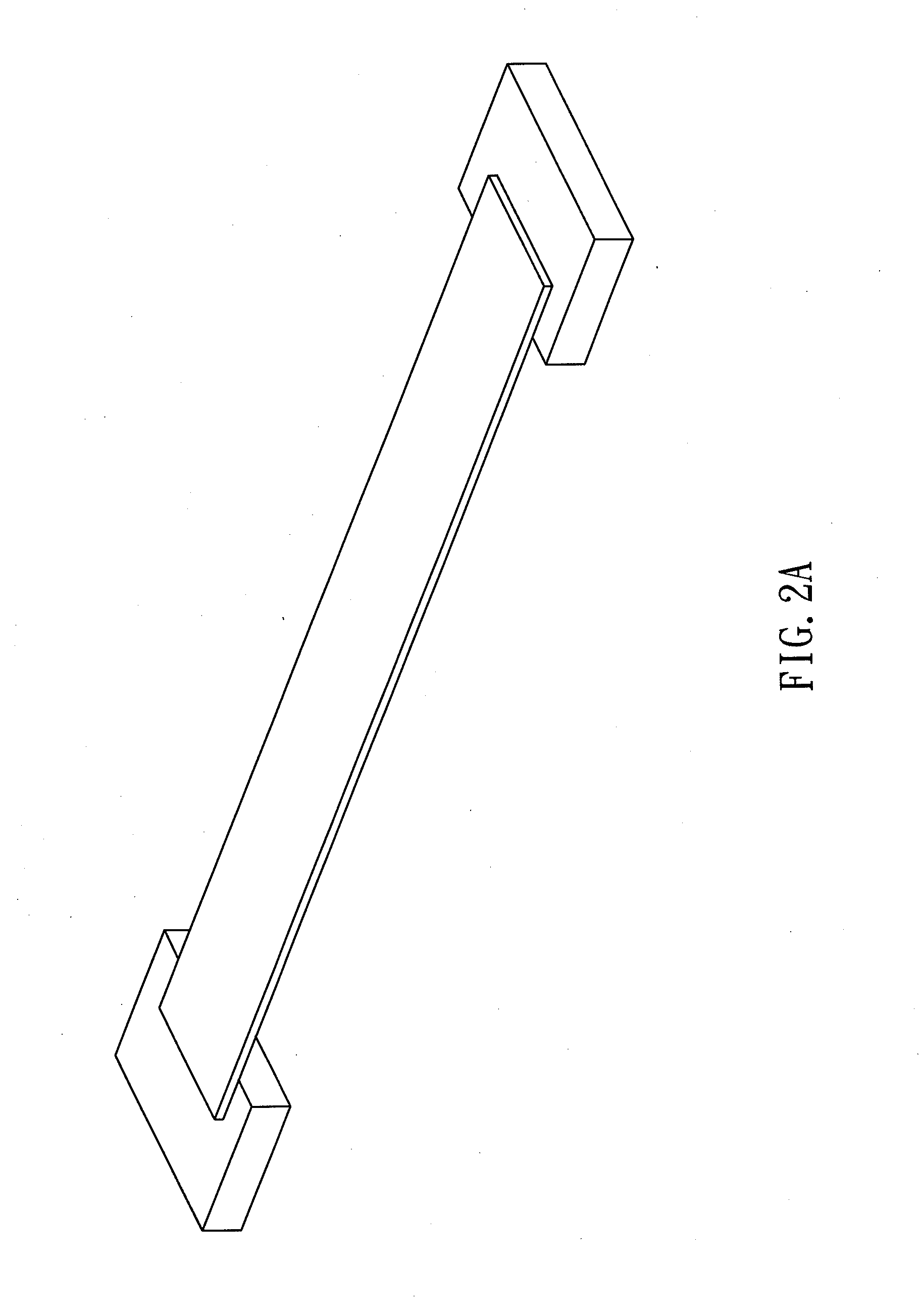
[0048]FIG. 2B is a perspective view of a bridge pier that rigidity-controllable device of the present embodiment is mounted thereon, and FIG. 2A is a perspective view of a conventional bridge pier that there is no shake-absorbing unit mounted thereon.

[0049]As shown in FIG. 2B, the composite 11 of the present invention is mounted between bridge decks 21 and is fixed with screws 22. The rigidity and the damping factor of the composite 11 is controlled through a power supply (not shown in the figure) to show a shock-absorbing effect on the bridge pier.

[0050]In the rigidity-controllable device of the present invention, the rigidity and the damping factor of the composite can be adjusted. When the composite has high rigidity, it has high damping factor and can be used to absorb shock. When the composite has low rigidity, it has low damping factor and can be used as a supporting material. Hence, the rigidity-controllable device of the present can be applied to various fields, such as a br...


PUM


Abstract

A rigidity-controllable device and a damping-controllable shock-absorbing apparatus comprising the same are disclosed. The rigidity-controllable device of the present invention comprises: a composite comprising a polymer base and a nano-conductive material dispersed in the polymer base; and a power supply electrically connecting with the composite; wherein when the power supply electricity to the composite, temperature of the composite is increased and thus the rigidity of the composite is adjusted.

Description

CROSS REFERENCE TO RELATED APPLICATION[0001]This application claims the benefits of the Taiwan Patent Application Serial Number 100147109, filed on Dec. 19, 2011, the subject matter of which is incorporated herein by reference.BACKGROUND OF THE INVENTION[0002]1. Field of the Invention[0003]The present invention relates to a rigidity-controllable device and, more particularly to a rigidity-controllable device that the rigidity of a composite thereof is adjusted by electricity.[0004]2. Description of Related Art[0005]In the condition without any external force (for example, outer space), the shocks caused by the working of aircrafts such as artificial satellites and photovoltaic devices can only be eliminated by the materials contained therein, and there are no other external material can provide damping effect to the aircrafts to reduce these shocks. Hence, a material, which has better stability and is capable of enduring a level of vibration, has to be provided for the artificial sa...

Claims


Application Information

Patent Timeline
IPC IPC(8): F16F7/00
CPCF16F7/00B82Y30/00Y10S977/902F16F1/3615
Inventor HSU, WEN-KUANGWENG, MING-HSIAO
Owner NATIONAL TSING HUA UNIVERSITY
Why Eureka
Try Eureka