
Magnetic core for antenna, method for producing magnetic core for antenna, and antenna

A magnetic core and antenna technology, applied in the field of magnetic cores for antennas, manufacturing magnetic cores for antennas and antennas, can solve the problems of fragility, property degradation, cracks and other problems of ferrite, and achieve less brittleness and small curvature Effect

Active Publication Date: 2010-02-24
HITACHI METALS LTD
View PDF3 Cites 21 Cited by
  • Summary
  • Abstract
  • Description
  • Claims
  • Application Information

AI Technical Summary

Problems solved by technology

However, since ferrite is brittle, cracks can be generated in it even due to slight deformation
Therefore, when the key is dropped on the ground or when the user walks with the key in the trousers pocket, etc., cracks are generated due to the shock, deteriorating its properties.

Method used


Image

  • Magnetic core for antenna, method for producing magnetic core for antenna, and antenna
  • Magnetic core for antenna, method for producing magnetic core for antenna, and antenna
  • Magnetic core for antenna, method for producing magnetic core for antenna, and antenna

Examples


Embodiment Construction

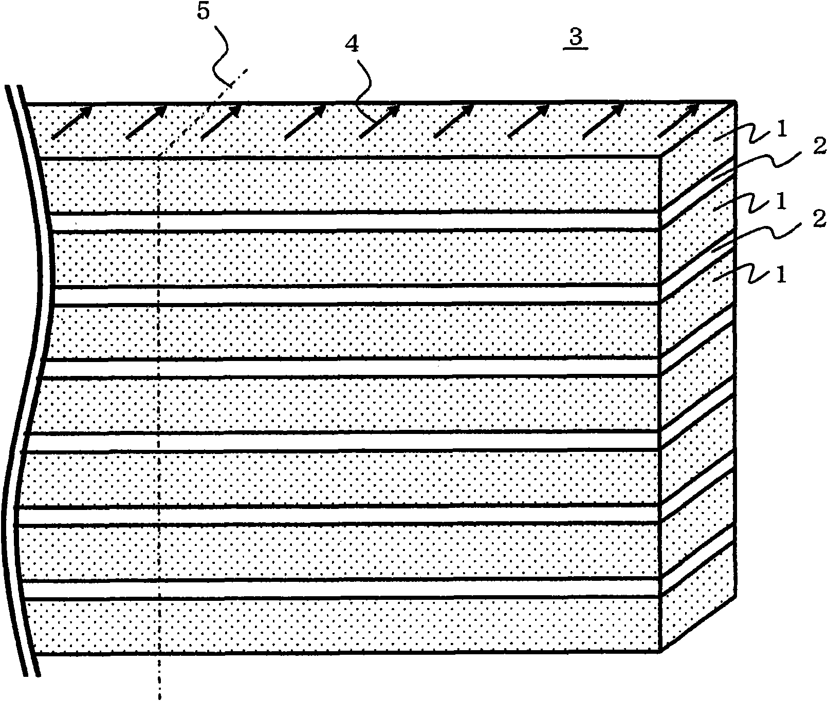
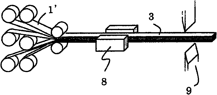
[0065] In the following, reference will be made to figure 1 , 2A and 2B describe a method of manufacturing a magnetic core for an antenna according to the present invention.

[0066] figure 1 A stack 3 obtained by heat-treating thin metal strips 1 in a magnetic field and stacking thin metal strips 1 through an insulating layer 2 is shown. figure 1 The longitudinal (transverse) direction in is the longitudinal direction of a thin strip obtained by slitting a thin metal strip produced with a hyperquenching roll. A magnetic field is applied in a direction perpendicular to the longitudinal direction, reference numeral 4 designating the direction of the induced magnetic anisotropy. At the time of stacking, for example, thin metal strips 1 are coated with a polyamic acid solution as a precursor of polyimide resin, and pressure-bonded by roll pressing. Thus, the stacking process can be performed in a Roll-to-Roll process, so continuous manufacturing is possible. The laminate ...


PUM

PropertyMeasurementUnit
Widthaaaaaaaaaa

Abstract

Disclosed is a method for producing a magnetic core for antenna wherein thin metal strips are laminated. This method for producing a magnetic core for antenna is characterized in that a metal thin band is processed into strips having a width of the aimed magnetic core for antenna, then the thin strips are stacked through a resin layer to form a laminate, and after that the laminate is cut into a length of the aimed magnetic core for antenna.

Description

technical field [0001] The present invention relates to a strip-shaped magnetic core for an antenna using a lamination of thin metal strips having soft magnetism, and an antenna using the magnetic core for an antenna, which is used for keyless entry of vehicles and the like system. Background technique [0002] Conventionally, an antenna having a ferrite core has been used for an RFID (wireless IC tag) of a keyless entry system of a vehicle or the like. However, since ferrite is brittle, cracks can be generated therein even due to slight deformation. Therefore, when the key is dropped on the ground or when the user walks with the key in his trousers pocket, etc., cracks are generated due to the shock, deteriorating its properties. In order to solve the above-mentioned problems, an amorphous thin metal strip has been used as a material for a magnetic core of an antenna, and a laminated amorphous thin metal strip has been used as a magnetic core. [0003] For example, Paten...

Claims


Application Information

Patent Timeline
IPC IPC(8): H01F41/02H01F17/04H01F27/24H01Q7/06
CPCH01F1/15316H01F3/02H01Q7/08H01Q7/06H01F1/15391H01F1/15383H01F27/324H01F41/0233H01F10/138
Inventor 岸大辅森次仲男古井义继
Owner HITACHI METALS LTD
Learn More