Image processing device

a technology for processing devices and subject shapes, which is applied in the field of vehicle image processing devices, can solve problems such as blind spots where the driver cannot visually recognize, and achieve the effect of reducing the degree of bent of a subject shape and improving visibility

Active Publication Date: 2015-05-14
MITSUBISHI ELECTRIC CORP
View PDF3 Cites 22 Cited by
  • Summary
  • Abstract
  • Description
  • Claims
  • Application Information

AI Technical Summary

Benefits of technology

[0011]According to the claimed invention, the degree of bent of a subject shape is reduced even at a boundary portion between camera images, and thus visibility can be improved.

Problems solved by technology

However, a blind spot sometimes arises where the driver cannot visually recognize due to the vehicle body of its own or existing obstacles.

Method used


Image

  • Image processing device
  • Image processing device
  • Image processing device

Examples


embodiment 1

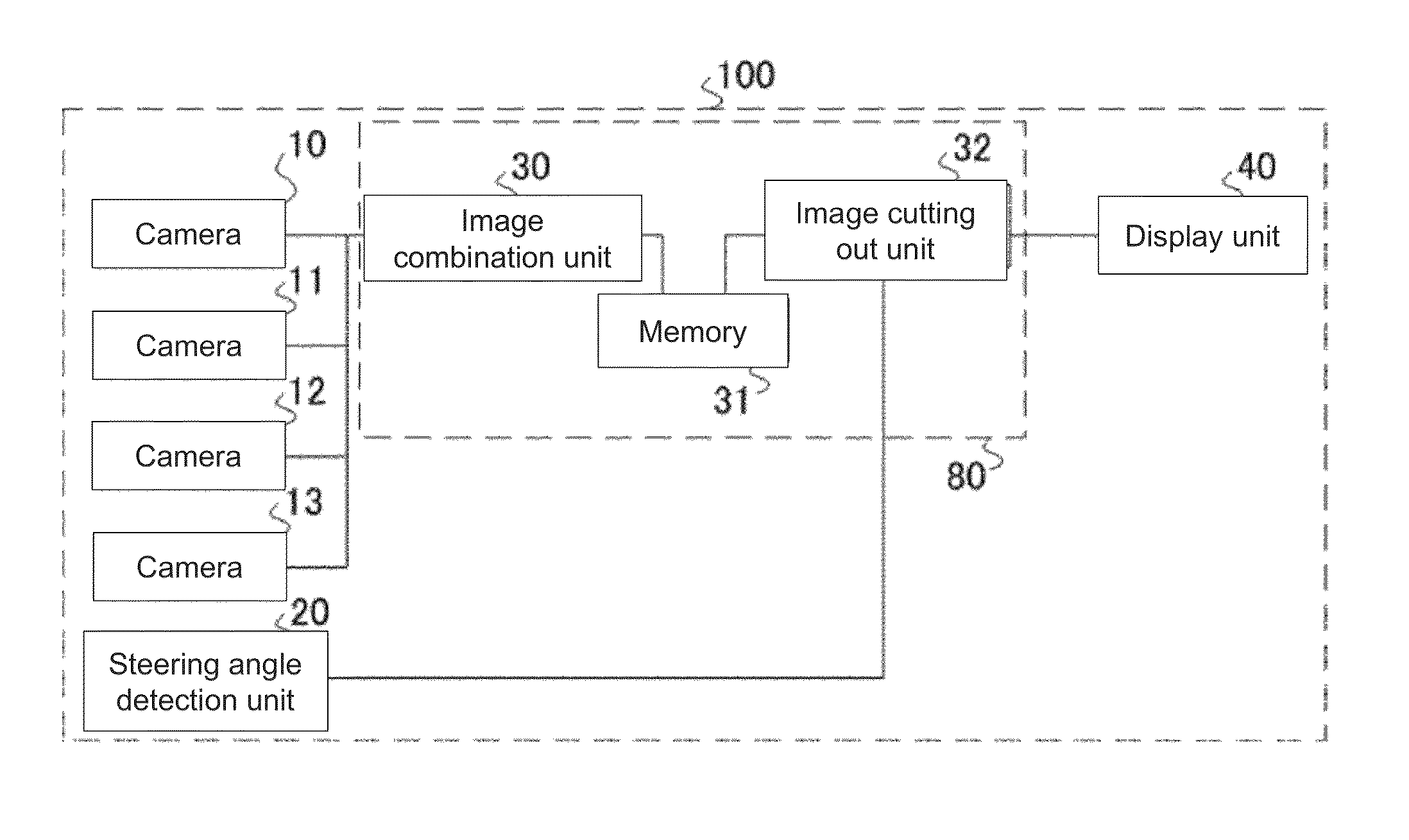
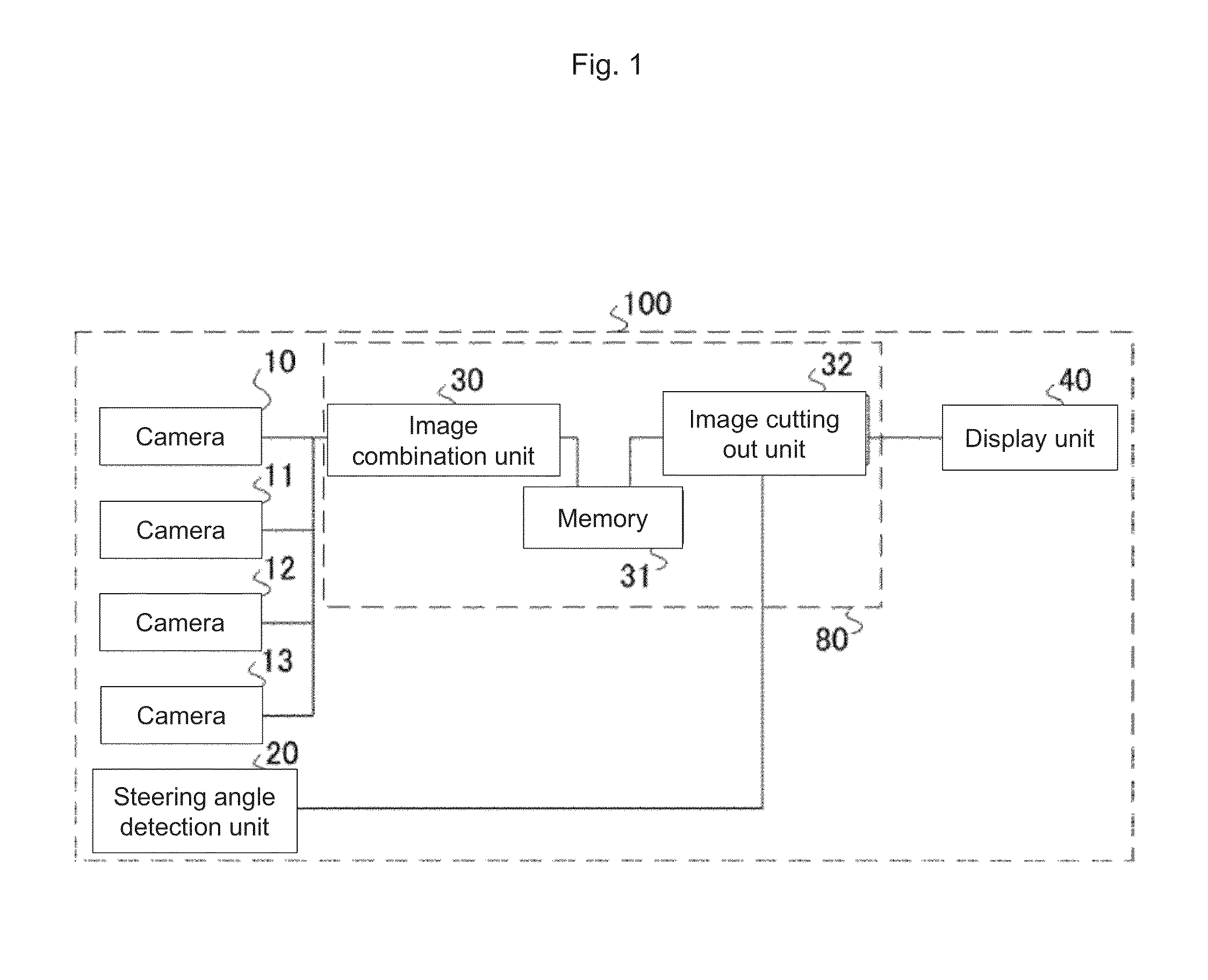
[0024]FIG. 1 is a block diagram showing a configuration of a driving support device 100 in Embodiment 1. The driving support device 100 according to the present invention includes cameras 10, 11, 12, and 13, a steering angle detection unit 20, an image combination unit 30, an image cutting out unit 32, and a display unit 40. The driving support device 100 may further include a memory 31. An image processing device 80 according to Embodiment 1 includes the image combination unit 30. The image processing device 80 may include the image cutting out unit 32. The image processing device 80 may include the memory 31.

[0025]The cameras 10, 11, 12, and 13 capture surrounding images of a vehicle. The steering angle detection unit 20 detects a turning angle of a steering wheel of the vehicle. “Turning angle of a steering wheel” means an angle when the steering wheel is turned. “Turning a steering wheel” means an operation of changing a vehicle traveling direction by turning the steering wheel....

embodiment 2

[0044]FIG. 5 is a block diagram showing a driving support device 110 in Embodiment 2. The driving support device 110 according to the present invention includes cameras 10, 11, 12, and 13, a steering angle detection unit 20, an image combination unit 30, an image cutting out unit 32, a distance information acquisition unit 35, and a display unit 40. The driving support device 110 may further include a memory 31. An image processing device 81 according to Embodiment 2 includes the image combination unit 30 and the distance information acquisition unit 35. The image processing device 81 may include the image cutting out unit 32. The image processing device 81 may include the memory 31.

[0045]The driving support device 110 further includes the distance information acquisition unit 35, which is the difference from the driving support device 100. The cameras 10, 11, 12, and 13, the steering angle detection unit 20, the image combination unit 30, the image cutting out unit 32, the display ...

embodiment 3

[0100]FIG. 10 is a block diagram showing a driving support device 120 in Embodiment 3. The driving support device 120 according to the present invention includes cameras 10, 11, 12, and 13, a steering angle detection unit 20, an image combination unit 30, a front image cutting out unit 33, a rear image cutting out unit 34, and a display unit 40. The driving support device 120 may further include a memory 31.

[0101]An image processing device 82 according to Embodiment 3 includes an image combination unit 30. The image processing device 82 may include the front image cutting out unit 33 and the rear image cutting out unit 34. The image processing device 82 may include the memory 31.

[0102]The driving support device 120 is different from the driving support device 100 in a manner that the image cutting out unit 32 includes the front image cutting out unit 33 and the rear image cutting out unit 34. The cameras 10, 11, 12, and 13, the steering angle detection unit 20, the image combination...


PUM


Abstract

An image processing device 81 includes a distance information acquisition unit 35 and an image combination unit 30. Based on positions of a common subject on a plurality of images captured by a plurality of cameras 10, 11, 12, and 13 for capturing surrounding images of a vehicle, the distance information acquisition unit 35 calculates a first subject distance from a vehicle reference position O to the common subject, and calculates, based on the first subject distance, a second subject distance to a subject captured by one of the plurality of cameras 10, 11, 12, and 13. Based on the first subject distance and the second subject distance, the image combination unit 30 converts the captured images in which the plurality of cameras 10, 11, 12, and 13 are employed as viewpoints to images in which the reference position O is employed as a viewpoint, and combines the converted images on a single plane of projection.

Description

TECHNICAL FIELD[0001]The present invention relates to an in-vehicle image processing device for assisting a driver to check the surroundings of a vehicle by capturing a blind spot, arising when driving the vehicle, by a camera and generating an image thereof.BACKGROUND ART[0002]When driving a vehicle, the driver visually checks a surrounding status of the vehicle. However, a blind spot sometimes arises where the driver cannot visually recognize due to the vehicle body of its own or existing obstacles. “Blind spot” means an area of which one cannot get a view from a certain angle. Here, it means an area of which the driver cannot get a view. “Vehicle of its own” means a vehicle that the driver is on. In order to assist the driver to recognize such a blind spot, a technology is proposed in which an image of the surroundings of vehicle is captured by a camera mounted on the vehicle body and the image is displayed on a screen of a display device installed in the vehicle. The followings ...

Claims


Application Information

Patent Timeline
Patent Type & Authority Applications(United States)
IPC IPC(8): B60R1/00
CPCB60R1/00B60R2300/607B60R2300/605B60R2300/105
Inventor FUJITA, TAKEOMATOBA, NARIHIROMITSUGI, TATSUYA
Owner MITSUBISHI ELECTRIC CORP
Why Eureka
Try Eureka