
Automatic Injection Device For Two-Chamber Ampoules

an injection device and ampoules technology, applied in the direction of infusion needles, infusion syringes, other medical devices, etc., can solve the problems of requiring a great deal of patient attention, and achieve the effect of improving patient comfort and safety, and simple mechanical design

Active Publication Date: 2008-08-07
BAYER INTELLECTUAL PROPERTY GMBH
View PDF3 Cites 85 Cited by
  • Summary
  • Abstract
  • Description
  • Claims
  • Application Information

AI Technical Summary

Benefits of technology

[0006]It is the object of the invention to improve an injection device for a two-chamber ampoule through automatization of the sequences in such a way that the handling comfort and safety for the patient are improved, while providing for a simple mechanical design.
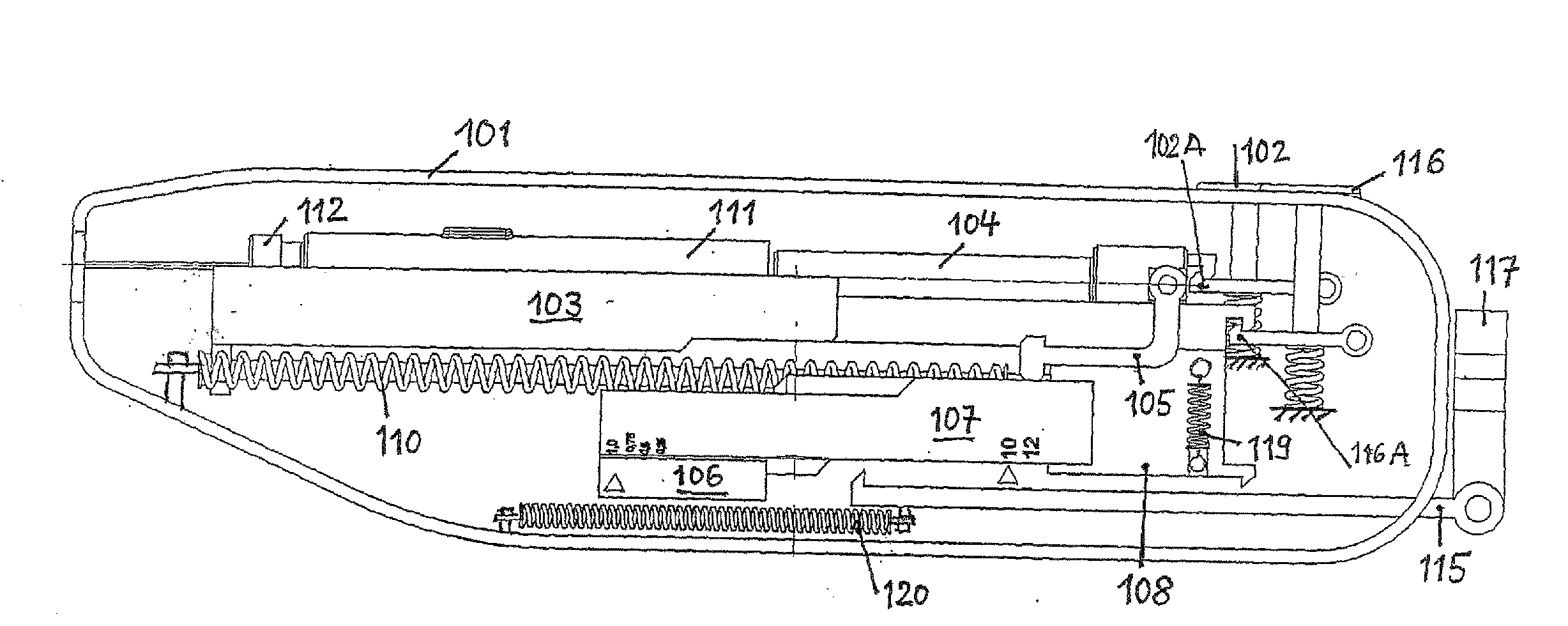
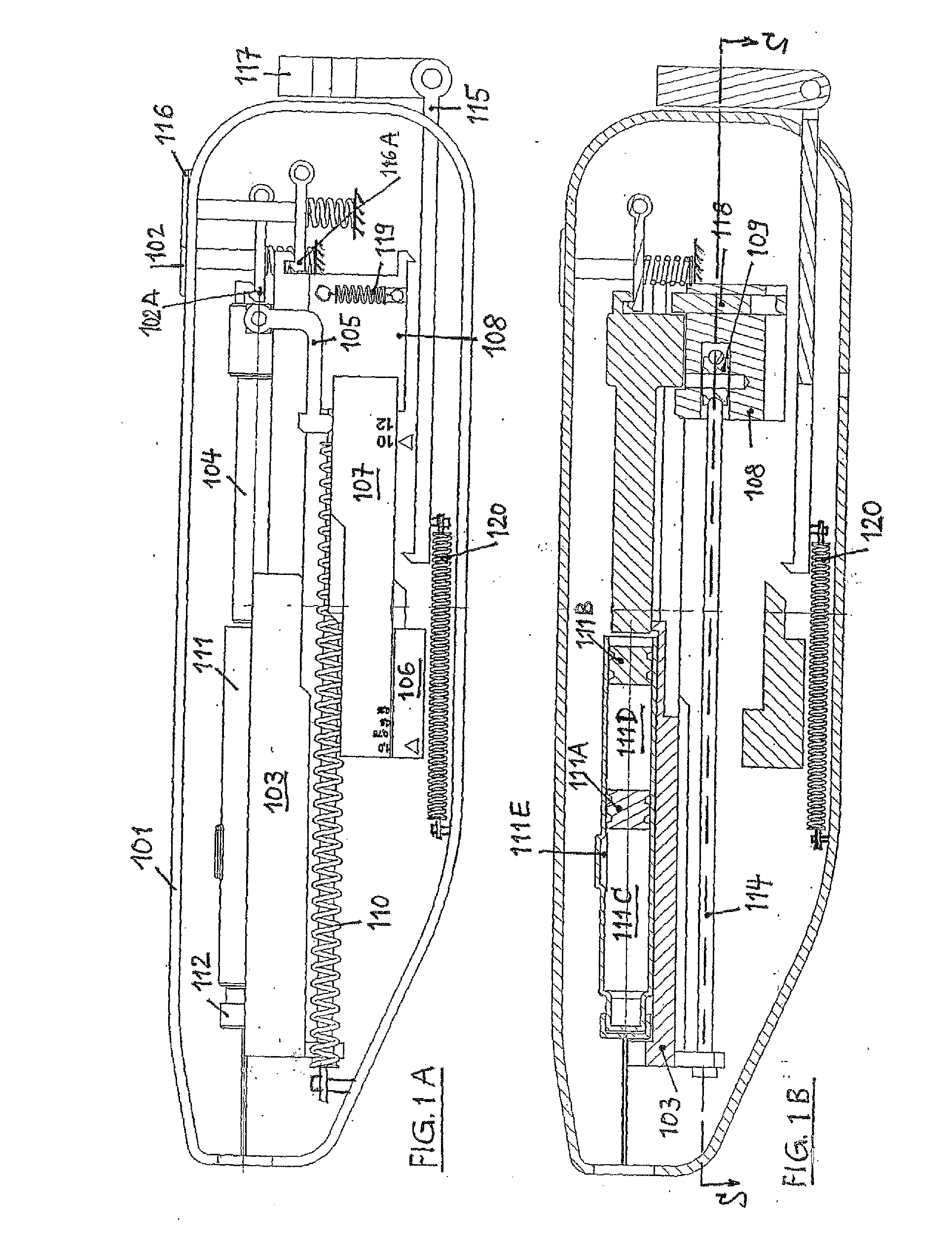
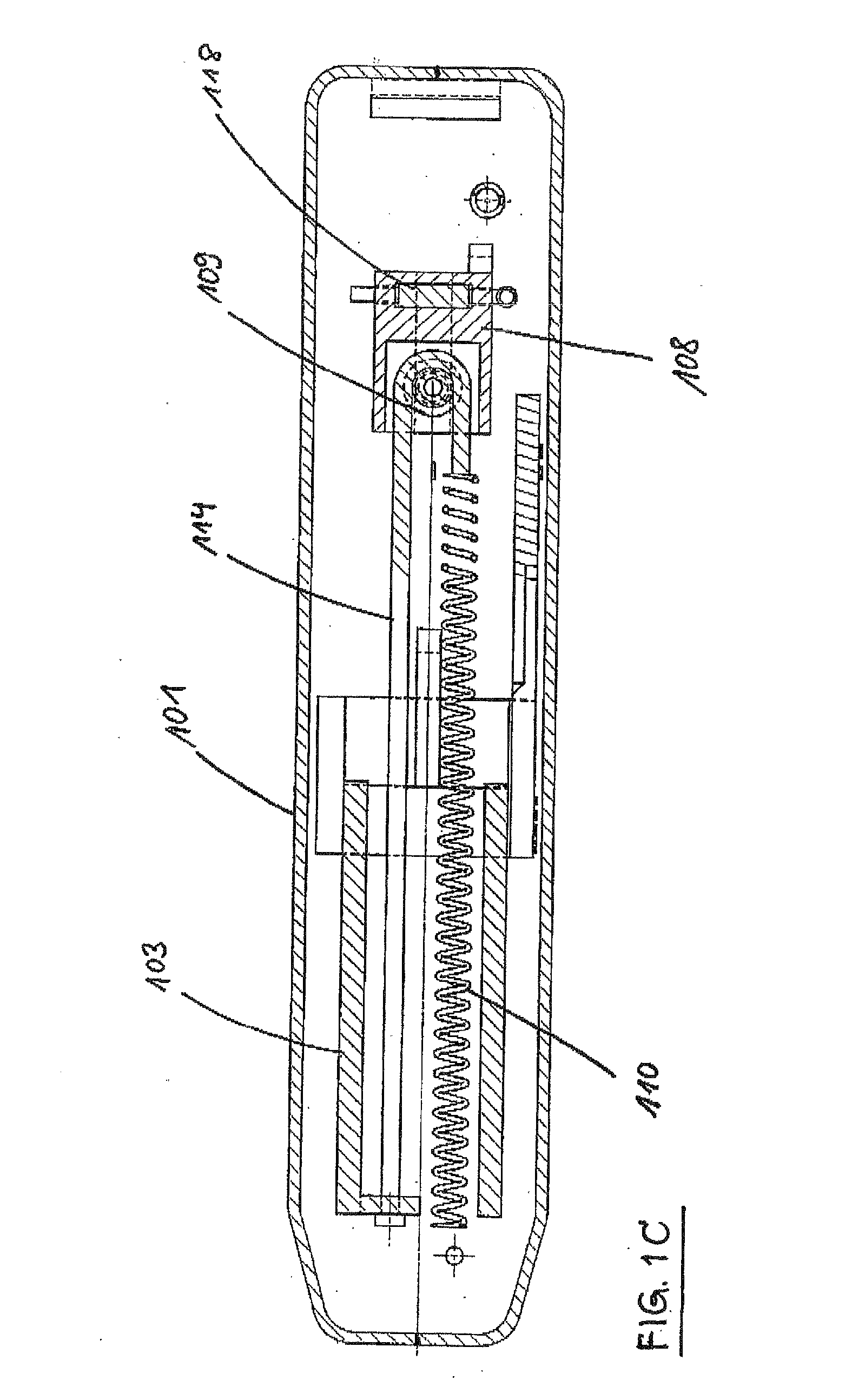
[0009]The underlying inventive idea lies in effecting the sequence of the strokes solely by means of a simple drive mechanism, namely a traction-cable system. To this effect, the stroke that is carried out by the tappet upon activation of the two-chamber ampoule, is divided into a preceding mixing stroke and an injection stroke, which are interrupted by the insertion stroke. This ensures that the insertion of the needle into the injection site takes place only after mixing of the two active substances has occurred and was optionally assessed as correct by the patient through a window.

Problems solved by technology

Controlling these process sequences takes place manually, however, and handling accordingly requires great attention on the part of the patient, especially also since no provision is made for a withdrawal of the needle after the completed injection.

Method used


Image

  • Automatic Injection Device For Two-Chamber Ampoules
  • Automatic Injection Device For Two-Chamber Ampoules
  • Automatic Injection Device For Two-Chamber Ampoules

Examples


Embodiment Construction

[0026]To inject the active substance, a two-chamber ampoule 111 is used. An ampoule of this type (FIG. 1B) has two pistons 111A, 111B, resulting in two initially independent chambers 111C, 111D. Into the first, inner chamber 111C, which faces the needle 112, powdered Betaferon is filled, for example, and into the second, outer chamber 111D, a NaCl solution is filled.

[0027]If a tappet 104 is now pressed against the outer piston 111B, the inner piston 111A is initially displaced as well, since the NaCl solution hydraulically transfers the force of the tappet onto the inner piston 111A. As soon as the inner piston 111A has passed an overflow channel 111E in the form of a groove-like convexity in the outer wall of the ampoule 111, it comes to a standstill and the NaCl solution flows through this overflow channel 111E into the inner chamber 111C and mixes with the Betaferon. After the mixing process, the injection then takes place (after the insertion stroke) through the continued moveme...


PUM


Abstract

An injection device for holding and activating a two-chamber ampulla has components whose relative movement causes the pistons of the two-chamber ampulla to be moved in order to mix the substances, as well as devices for injecting the product which is mixed in this way. For this purpose, a receptacle (103) into which the two-chamber ampulla (111) can be inserted and secured is held in a housing (101), and the receptacle (103) can be displaced by means of a carriage (108). A tappet (104) which acts on the pistons (111A, 111B) is movably held in the receptacle (103). A traction cable (114) which is deflected by means of a roller (109) which is mounted on the carriage (108) and one of whose ends is connected to the receptacle (103) and the other end of which is connected to a tension spring (110) which is held on the housing (101) is provided in order to carry out a mixing stroke, insertion stroke, injection stroke and a return stroke. Devices which can be activated automatically and / or manually between the housing (101), receptacle (103), tappet (104) and carriage (108) control their alternating coupling to the traction cable (114) and thus the sequence of the mixing stroke, insertion stroke, injection stroke and return stroke. The invention thus provides a partially automatic injection device for two-chamber ampullas whose handling comfort and safety for the patient are substantially improved.

Description

[0001]For the treatment of a multitude of illnesses, such as diabetes, which are now widespread, patients must inject themselves independently with the needed amount of an active substance / medicament, using a syringe or a carpule. To make this safer and easier, a multitude of injection devices are known that incorporate a largely automatic sequence of inserting the needle, injecting the active substance and withdrawing the needle.PRIOR ART[0002]For the use of disposable hypodermic syringes, a number of devices are known for an automatic injection of the active substance that is contained in the syringe; WO 2005 / 011780 or WO 99 / 56805, for instance, reveal injection devices that permit a fully automatic sequence of the above-described processes while being simple to operate.[0003]In recent times it has become apparent that an improvement of the treatment result, or ensuring a medical success to begin with, requires the use of active substances that need to be mixed with another active...

Claims


Application Information

Patent Timeline
Patent Type & Authority Applications(United States)
IPC IPC(8): A61M5/24A61M5/46
CPCA61M5/2033A61M5/2066A61M5/2448A61M5/31555A61M5/3156A61M2005/206A61M5/31578A61M5/31591A61M5/326A61M5/46A61M5/31563A61M5/20A61M5/32
Inventor WEBER, WILFRIED
Owner BAYER INTELLECTUAL PROPERTY GMBH
Learn More