Fuel Injection Device for an Internal Combustion Engine

a fuel injection device and internal combustion engine technology, applied in the direction of electrical control, process and machine control, instruments, etc., can solve the problems of preventing the restart of the internal combustion engine, preventing the degassing of fuel, and completely tightening the high-pressure region

Inactive Publication Date: 2008-08-07
ROBERT BOSCH GMBH
View PDF3 Cites 2 Cited by
  • Summary
  • Abstract
  • Description
  • Claims
  • Application Information

AI Technical Summary

Problems solved by technology

In new fuel injection devices, the high-pressure region is completely leak-tight.
Upon subsequent cooling, the complete leak-tightness of the high-pressure region can cause a degassing of the fuel to occur.
This impedes the restarting of the internal combustion engine since it is first necessary to displace the gas in the high-pressure region.

Method used


Image

  • Fuel Injection Device for an Internal Combustion Engine
  • Fuel Injection Device for an Internal Combustion Engine
  • Fuel Injection Device for an Internal Combustion Engine

Examples


Embodiment Construction

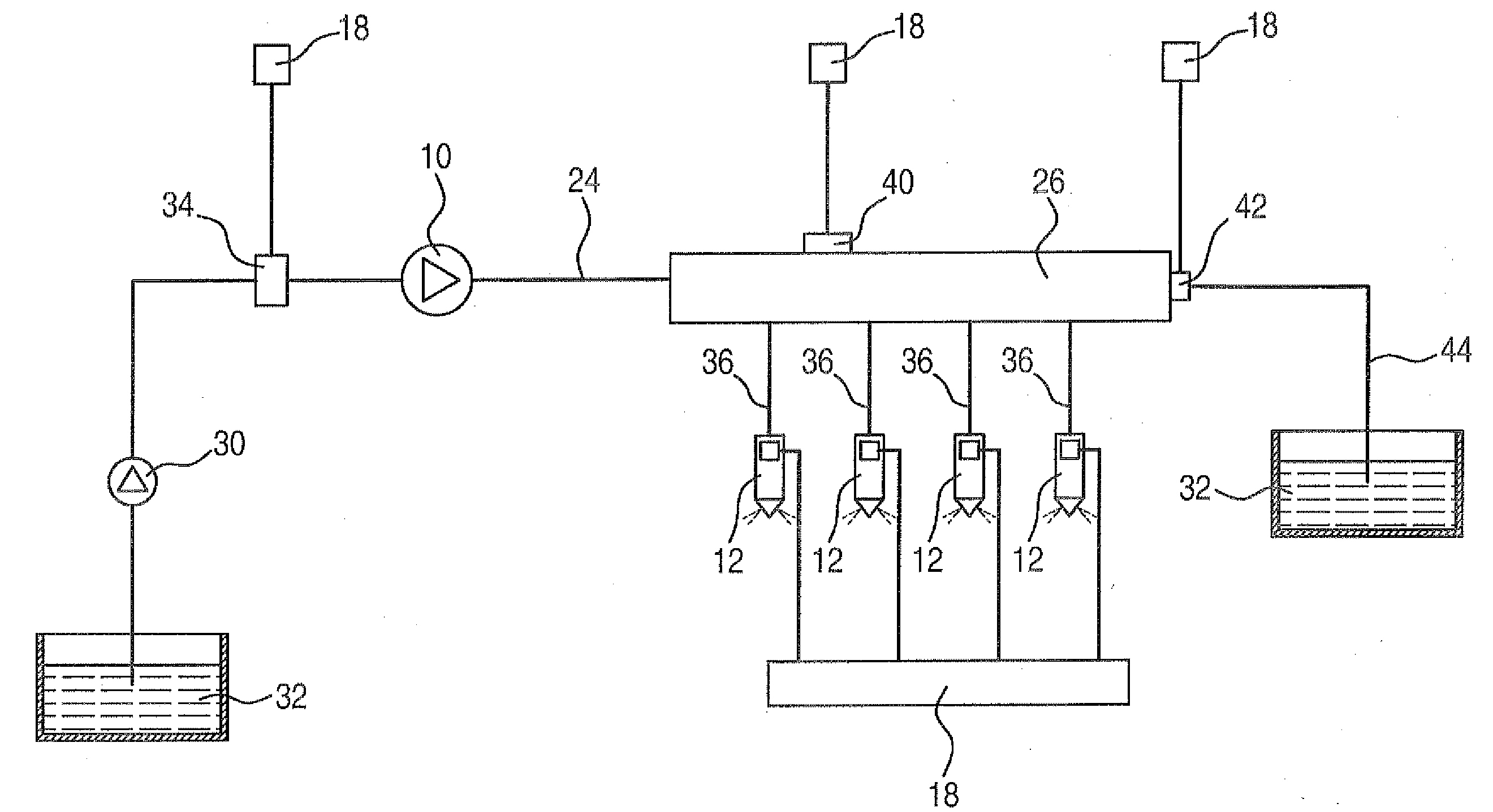
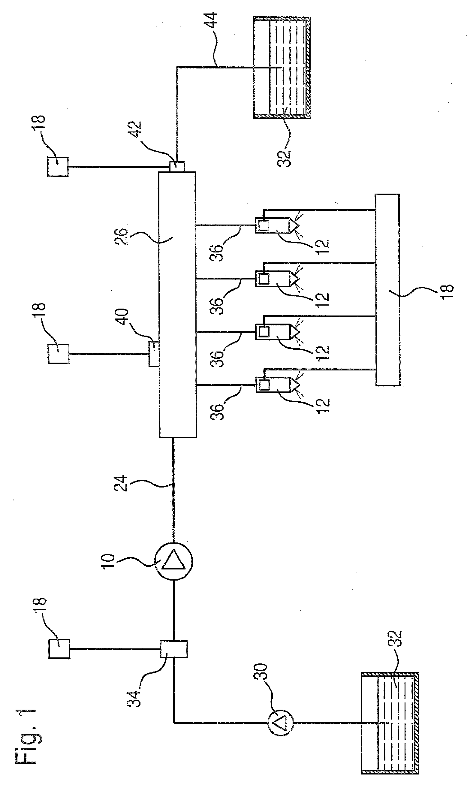
[0010]FIGS. 1 through 4 show a fuel injection device for a multicylinder internal combustion engine that is preferably an autoignition engine of a motor vehicle. The fuel injection device has a high-pressure pump 10 that delivers the fuel at a high pressure. Each cylinder of the internal combustion engine is provided with an injector 12 that is able to inject the fuel into the combustion chamber of the cylinder. Only some of the injectors 12 are shown in FIGS. 1 through 3; other injectors up to the last injector 12d are indicated by dots.

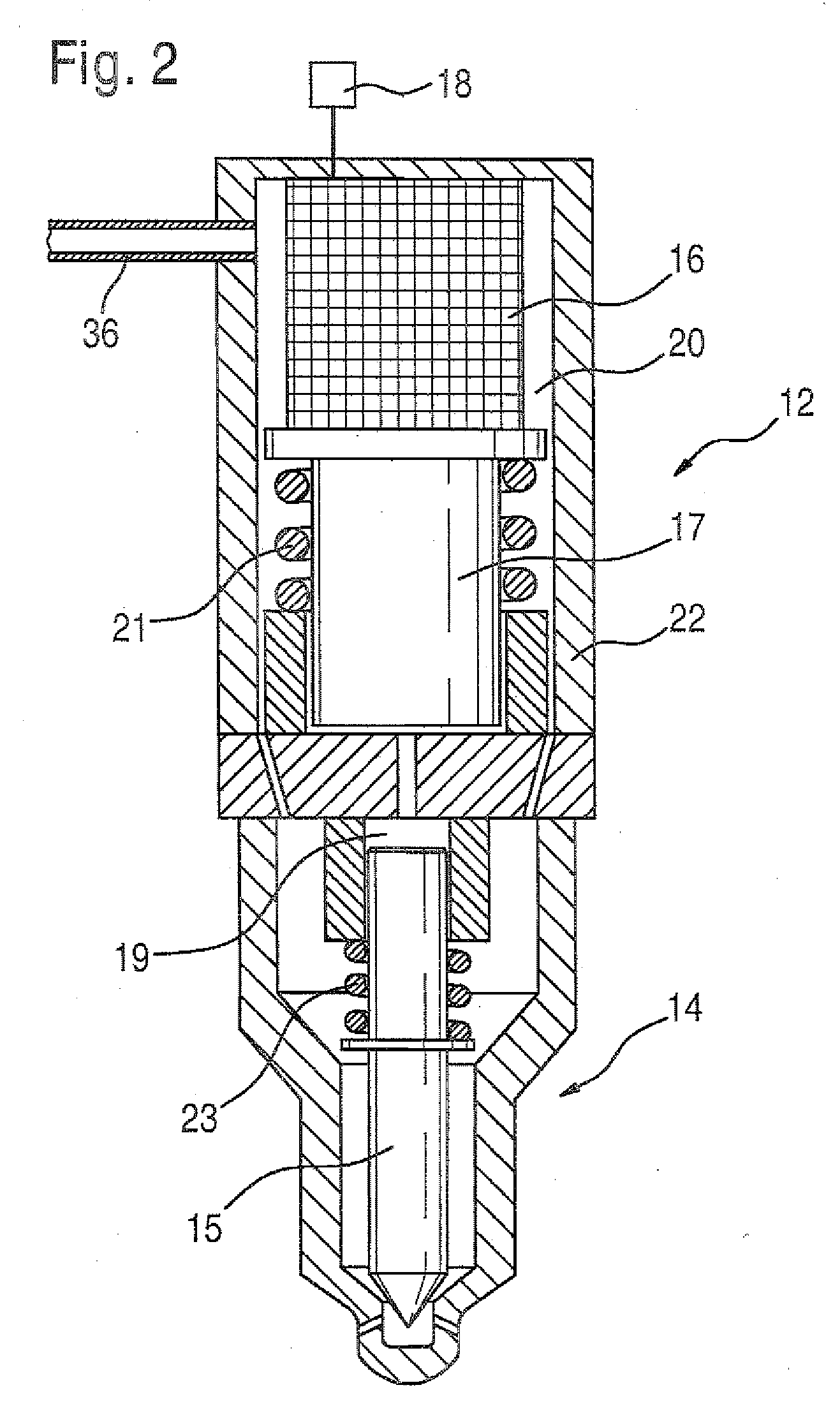
[0011]As shown in FIG. 2, the injector 12 has a fuel injection valve 14, which injects fuel into the combustion chamber of the cylinder, and has an electrically triggered actuator 16. The actuator controls the opening and closing motion of an injection valve member 15 of the fuel injection valve 14. The actuator 16 is preferably a piezoelectric actuator, whose size changes as a function of an electrical voltage applied to it. This size change can pe...


PUM


Abstract

A fuel injection device comprising a high-pressure pump supplying a fuel to a high-pressure area in which an injector for injecting fuel into an internal combustion engine cylinder is arranged. An electric control unit for controlling fuel injection by at least one injector is provided. A pressure adjusting valve which adjusts a pressure in the high-pressure area and controls a connection between said high pressure area and a low-pressure fuel-filled area is controlled by the control unit. When the pressure adjusting valve is not controlled by the control unit it is placed in an open switching position in such a way that the connection between the high- low-pressure areas is opened, thereby preventing a gas formation in the high pressure area when the internal combustion engine is switched off and the fuel is cooled.

Description

PRIOR ART [0001]The invention is based on a fuel injection device for an internal combustion engine as generically defined by the preamble to claim 1.[0002]A fuel injection device of this kind is known from DE 100 04 617 A. This fuel injection device has a high pressure pump that delivers fuel into a high-pressure region in which for example one high-pressure accumulator, a so-called rail, is provided. An injector for fuel injection is provided for each cylinder of the engine; each injector is connected to the high-pressure accumulator via a hydraulic line. An electric control unit is provided for controlling the fuel injection by means of the injectors. Both the lines to the injectors and the injectors themselves are components of the high-pressure region. A pressure control valve that is triggered by the control unit is provided for setting a certain pressure in the high-pressure region. The pressure control valve controls a connection between the high-pressure region and a low-pr...

Claims


Application Information

Patent Timeline
Patent Type & Authority Applications(United States)
IPC IPC(8): F02D41/30
CPCF02M51/0603F02M51/061F02M2200/703F02M63/0225F02M63/025F02M63/0052F02M63/02F02M63/00F02M59/46
Inventor PAUER, THOMAS
Owner ROBERT BOSCH GMBH
Why Eureka
Try Eureka