Fluid handling device having a spring mechanism

a technology of spring mechanism and handling device, which is applied in the field of spring mechanism of handling device, can solve the problems of blood cell damage, blood contamination, noticeable loss of liquid, etc., and achieve the effect of increasing the service life and volume of such a spring mechanism

Inactive Publication Date: 2017-08-08
SMITHS MEDICAL DEUTLAND
View PDF28 Cites 0 Cited by
  • Summary
  • Abstract
  • Description
  • Claims
  • Application Information

AI Technical Summary

Benefits of technology

[0011]According to an embodiment, a fluid handling device may have: a receiving container with a piston arranged therein in a displaceable manner, such that the volume of a fluid receiving reservoir may be changed by a displacement of the piston; an actuation mechanism configured to displace a carrier bearing upon actuation of the former; and a spring mechanism configured to transfer a force from the carrier bearing to the piston so as to effect, in response to displacement of the carrier bearing in a first direction, a displacement of the piston within the receiving container such that a volume of the fluid reservoir is increased, the actuation mechanism including a rotary knob with a thread mechanism, the carrier bearing being mounted on a thread element including a thread, the thread mechanism engaging with the thread of the thread element so that the displacement of the carrier bearing may be effected by a rotation of the rotary knob.
[0012]The present invention is based on the finding that by decoupling the piston from the actuation mechanism and by directly moving it via the spring mechanism, fast actuation of the actuation mechanism is now possible without causing excessive negative pressure in the sampling system, due to which otherwise, e.g., the vascular wall of a blood vessel in the patient might collapse, or degassing of the blood sampled from the patient might occur. Rather, by actuating the actuating mechanism, a spring mechanism is tensioned which causes, by releasing the tensioning energy in a slow and controlled manner, the piston to be lifted only at a moderate lifting speed and / or a lifting speed which is predefined accordingly and which results, e.g., in limited negative pressure for pulling the liquid and for sampling the patient's blood.
[0013]This results in the advantage that degassing of a liquid located in the line adjoining an opening of the reservoir, and of the blood sampled is avoided, and that as compared to conventional approaches, the risk of a vascular wall collapsing is clearly reduced.

Problems solved by technology

The initially drawn amount of infusion solution and blood should not be recirculated to the patient since, due to the syringe aspiration process, blood cells are damaged and contamination of the blood may occur.
When blood sampling is performed frequently, this drawing of mixed blood prior to each blood sampling without subsequent recirculation leads to a noticeable loss of liquid.
However, this involves extensive handling and involves the risk—in addition to the risk that contaminants, germs and other pathogens are introduced into the system—that the hospital personnel might be injured and infected by the needle while removing same, which has already led to AIDS or hepatitis infections in hospital personnel before.
However, with said blood sampling device, the problem arises that the temporary storage is not fully emptied in the event of reinfusion of the patient's blood, so that residual blood will coagulate there.
If the above-mentioned processes are performed several times, it may therefore occur that coagulated residual blood returns to the patient's blood circulation from the temporary storage and highly endangers said patient.
However, it becomes apparent that even with such a provision within a closed blood sampling system attached to a patient over a relatively long period (e.g. several days), it cannot be ensured that the inner space of the blood sampling system, in particular of the temporary storage, is not contaminated by introduced germs.
In addition, conventional approaches to blood sampling by means of a temporary storage have the disadvantage that in many cases it cannot be ensured that blood and / or infusion solution is not aspirated out of the patient and / or the pressure measurement line at too high a negative pressure.
Too high a negative pressure caused by, e.g., excessive pulling of the piston may result in that degassing occurs which involves corresponding bubble formation taking place in the blood, and that the blood-vessel wall collapses and / or that vascular obstruction occurs, which may result in necrotizing of tissue right up to a patient's death, depending on the arterial sampling site in the patient.
Notwithstanding the above, the process involves a large amount of time on account of the care that is taken.
Finally, a temporary storage of a closed blood system makes sterilization by means of, e.g., ETO gas more difficult in a state wherein the temporary storage is in a state in which it is assembled and already arranged, e.g., in a gas-permeable packaging.

Method used


Image

  • Fluid handling device having a spring mechanism
  • Fluid handling device having a spring mechanism
  • Fluid handling device having a spring mechanism

Examples


Embodiment Construction

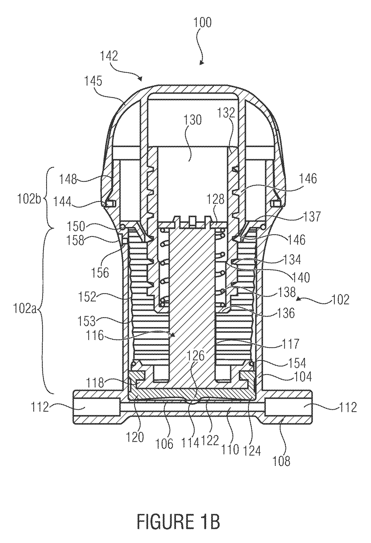
[0031]In the following drawings, identical or similar elements are provided with identical or similar reference numerals, repeated descriptions of the reference numerals being omitted.

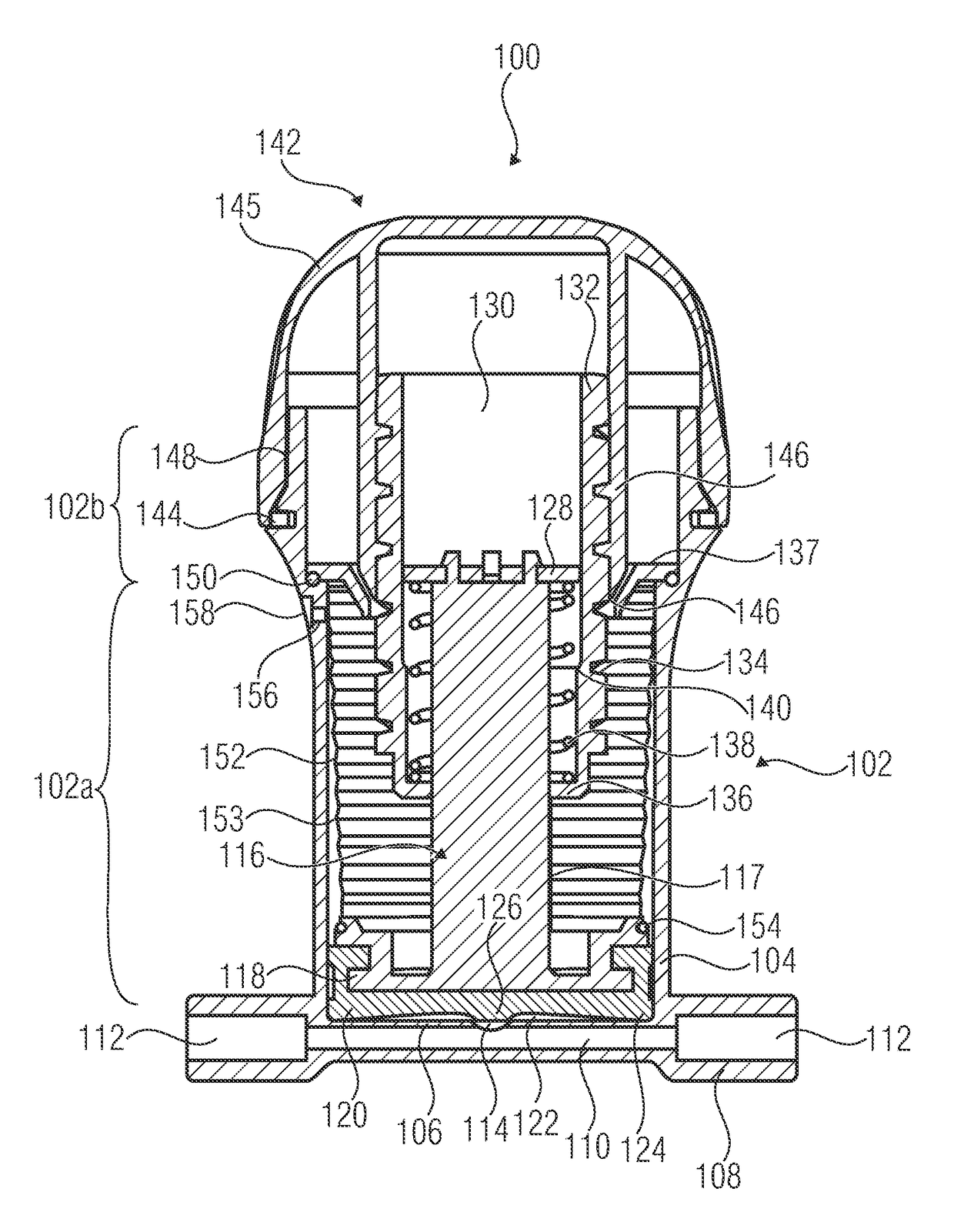
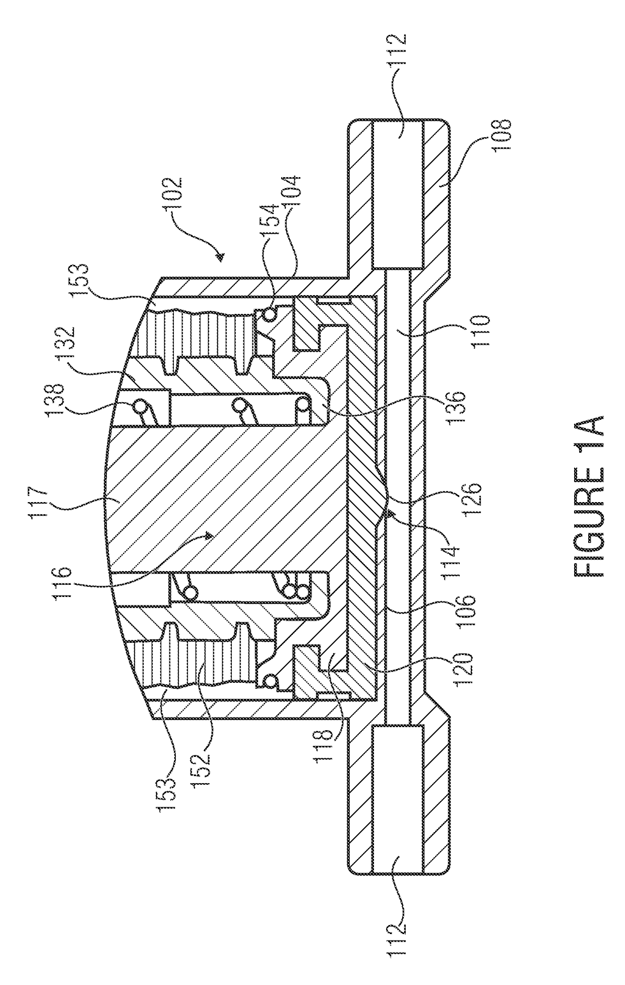
[0032]FIG. 1A shows a fluid handling device 100 in accordance with an embodiment of the present invention. Here, the fluid handling device 100 comprises a receiving container 102 having a side wall 104 as well as a planar (i.e. flat) container bottom 106. The receiving container 102 comprises a first portion 102a of cylindrical shape which adjoins the bottom 106 and is adjoined, in turn, by a second portion 102b of cylindrical shape which has a larger internal diameter. In addition, the receiving container 102 is attached to a connecting piece 108 comprising a flow channel 110 between two ports 112 of the connecting piece 108. A fluid opening 114 is centrally arranged, by way of example, in the flat container bottom 106 in such a manner that an exchange of fluid between the connecting channel 110 and t...


PUM


Abstract

A fluid handling device includes a receiving container with a piston arranged therein in a displaceable manner, such that the volume of a fluid receiving reservoir may be changed by a displacement of the piston. In addition, the fluid handling device includes an actuation mechanism configured to displace a carrier bearing upon actuation of the former. Finally, the fluid handling device includes a spring mechanism configured to transfer a force from the carrier bearing to the piston so as to effect, in response to displacement of the carrier bearing in a first direction, a displacement of the piston within the receiving container such that a volume of the fluid reservoir is increased.

Description

CROSS-REFERENCE TO RELATED APPLICATIONS[0001]This application is a continuation of copending International Application No. PCT / EP2012 / 057805, filed Apr. 27, 2012, which is incorporated herein by reference in its entirety, and additionally claims priority from German Application No. 10 2011 075 028.2, filed Apr. 29, 2011, which is also incorporated herein by reference in its entirety.[0002]The present invention relates to the technical field of fluid handling, and in particular, the present invention relates to a fluid handling device which may be used as a blood sampling device in medical technology.BACKGROUND OF THE INVENTION[0003]For drip infusion or direct blood pressure measurement, an infusion line or a catheter is usually inserted into a patient's vein or artery so as to sample blood, for example for examination purposes, from an externally accessible location of the infusion line. To this end, for example, taps or, in relatively recent systems, sampling sites may be provided ...

Claims


Application Information

Patent Timeline
Patent Type & Authority Patents(United States)
IPC IPC(8): A61B5/15A61B5/155A61M5/31A61M5/48
CPCA61B5/150244A61B5/1405A61B5/1427A61B5/150213A61B5/150236A61B5/150274A61B5/150946A61B5/150992A61B5/155A61B5/150328A61M5/3148A61M5/488A61B5/15003A61B5/150259A61B5/150305A61M5/14
Inventor WEBER, JOERG
Owner SMITHS MEDICAL DEUTLAND
Why Eureka
Try Eureka