Apparatus and Methods for Displaying and Determining Dependency Relationships Among Subsystems in a Computer Software System

a computer software and subsystem technology, applied in the field of dependency structures, can solve problems such as complex, difficult management of large-scale software development projects, and difficulty in determining interdependencies, and reduce the modularity of the system

Inactive Publication Date: 2008-08-07
LATTIX
View PDF9 Cites 14 Cited by
  • Summary
  • Abstract
  • Description
  • Claims
  • Application Information

AI Technical Summary

Problems solved by technology

In the field of software engineering, complex, large-scale software development projects can be difficult to manage.
These interdependencies, especially cyclical ones, can be difficult to manage.
While the architect of a software system might design the system to be modular initially, changes going into the system through time pressures and employee turnover in the software development team tend to decrease the modularity of the system.
Subsystems become more interdependent over time as other priorities take precedence over maintaining the modularity of the system, resulting in greater likelihood of problems being introduced into the system.
Further, as fewer software developers have knowledge of the overall system, the system becomes even more difficult to maintain.
As the dependency structure of the software system becomes more complex, the system becomes more difficult to maintain.
The complexity of displaying inter-relationships, for even the limited nine subsystem system of FIG. 1, is evident.
As the number of tables and their relationships increase these diagrams become hard to understand and to manage.
Furthermore, these diagrams normally do not display many important elements of the database such as packages, sequences and stored procedures.
Constructing a DSM where all the elements of the database are laid out in a flat structure would make the matrix large and hard to use.
There is no prior art guidance on how the hierarchy should be created for DSMs for databases.
Another difficulty in representing a database system and discovering optimal groupings of subsystems is related to the difficulty of processing “Synonyms”.
As the number of beans becomes large it becomes hard to make sense of these diagrams.
However, these diagrams do not take into account the file where the bean was specified.
A difficulty in using DSMs for representing databases and multi-domain systems is the large number of total elements and the fact many of the elements might be organized in a flat structure.
The large number of elements also makes it hard to visualize how changing one element will affect which other elements.

Method used


Image

  • Apparatus and Methods for Displaying and Determining Dependency Relationships Among Subsystems in a Computer Software System
  • Apparatus and Methods for Displaying and Determining Dependency Relationships Among Subsystems in a Computer Software System
  • Apparatus and Methods for Displaying and Determining Dependency Relationships Among Subsystems in a Computer Software System

Examples


Embodiment Construction

[0111]Definitions. As used in this description and the accompanying claims, the following terms shall have the meanings indicated, unless the context otherwise requires:

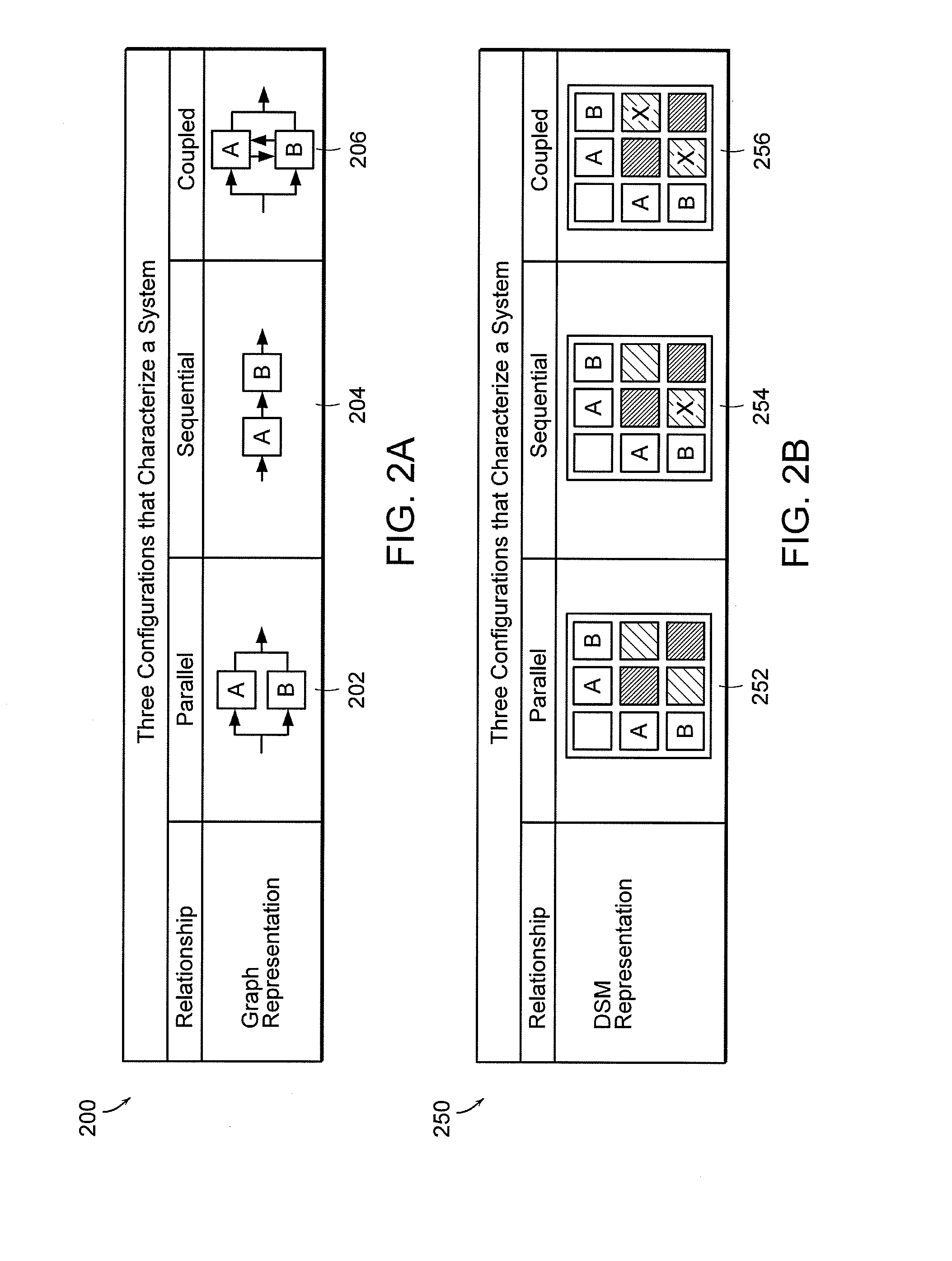
[0112]A “dependency structure matrix” (DSM) is a symmetric matrix, frequently a binary matrix, with matching horizontal and vertical axes, so that a corresponding row and column relate to the same subsystem and each cell has a value indicative of the strength of the dependency. A DSM has also been referred to in the literature as a “dependency structure matrix”, “dependency structure model”, and “adjacency matrix.”

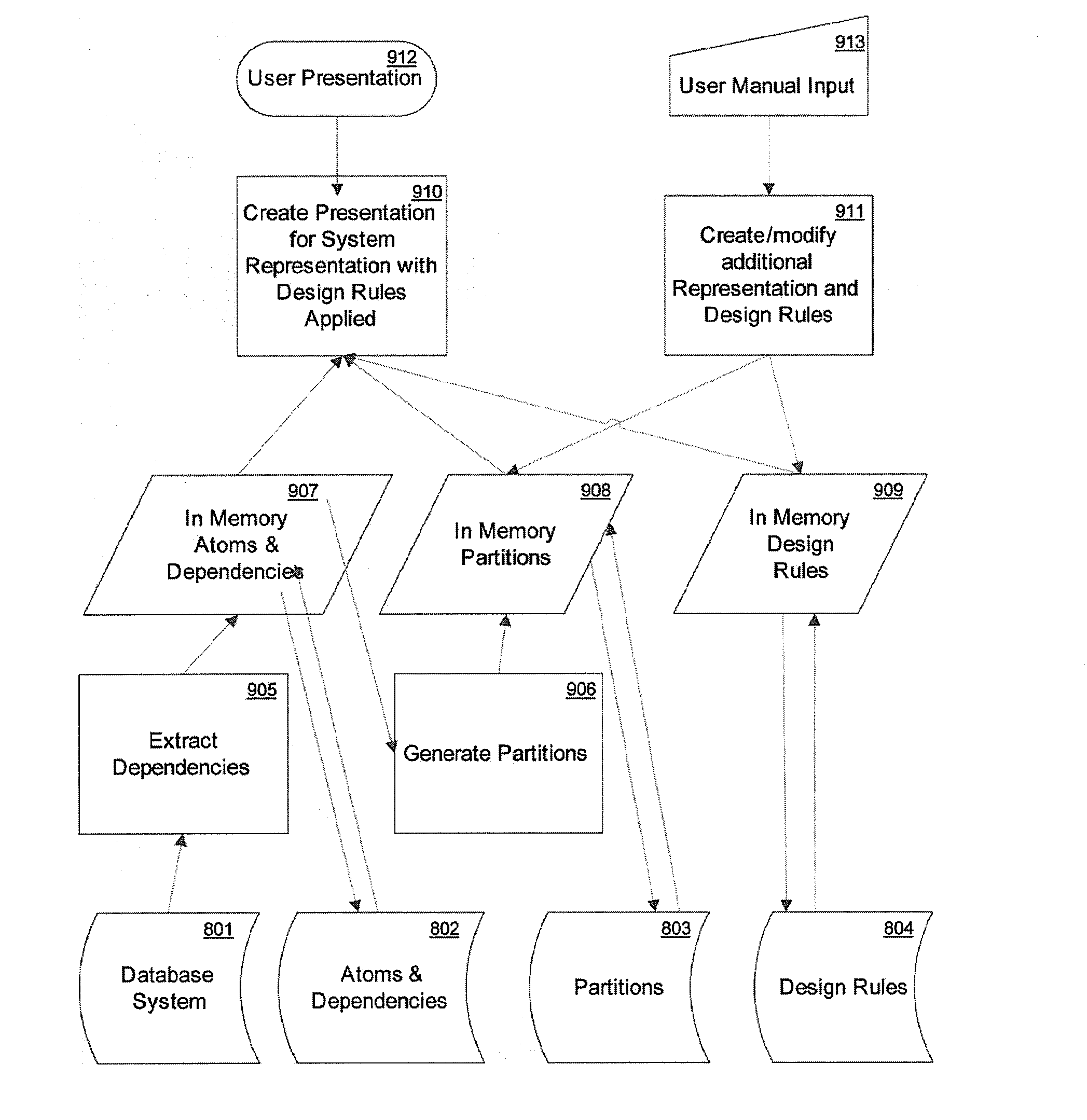
[0113]A “subsystem” means any portion of a software system, regardless of the level of granularity, so that a subsystem includes class, package, module, component, layer, file, directory, partition, etc, depending on the level of granularity selected and includes data on which computer instructions may operate. One example of a subsystem is a database.

[0114]A “domain” is a technology-based category of a sub...


PUM


Abstract

A method is provided for managing, in a computer system, design of a database system having a set of schemata. The method includes, in a first computer process, extracting dependencies from the database system and identifying the set of schemata. The method further includes, for each specific schema in the set of schemata, creating in a second computer process a partition that, in turn, contains a further partition for each element of the specific schema, so as to establish a hierarchy of partitions in accordance with the structure of the set of schemata. The method also includes storing a representation of the database system including subsystems, dependency relationships among the subsystems, and the hierarchy of partitions. Finally, the method includes providing a graphical output from the computer system, based on the stored representation, in which appears a display of the subsystems in a hierarchy of partitions within a dependency structure matrix, such matrix graphically indicating the dependency relationships among subsystems. Related apparatus and computer products are also provided.

Description

CROSS REFERENCE TO RELATED APPLICATIONS[0001]The present application claims priority from provisional application Ser. No. 61 / 018,849, filed Jan. 3, 2008, and from provisional application 60 / 886,791, filed Jan. 26, 2007. The present application is also a continuation in part of U.S. patent application Ser. No. 10 / 941,618, filed Sep. 15, 2004, which claims priority from provisional application 60 / 504,401, filed Sep. 19, 2003, and provisional application 60 / 605,923, filed Aug. 31, 2004. Each of these related applications is hereby incorporated herein by reference in its entirety.TECHNICAL FIELD[0002]The present invention relates to dependency structures, including systems and methods for determining and displaying dependency structures between subsystems of a software program that includes a database.BACKGROUND ART[0003]In the field of software engineering, complex, large-scale software development projects can be difficult to manage. Ideally, the design of a software system is kept a...

Claims


Application Information

Patent Timeline
Patent Type & Authority Applications(United States)
IPC IPC(8): G06F17/00
CPCG06F8/20G06Q10/10G06Q10/06G06F11/3604Y10S707/968Y10S707/972Y10S707/97
Inventor SANGAL, NEERAJWALDMAN, FRANCIS A.PARISI, CARL D.BRENNAN, STEPHEN C.
Owner LATTIX
Why Eureka
Try Eureka