Memory mapping

a memory system and mapping technology, applied in the field of flash memory systems, can solve the problems of large number of merge operations, large size of mapping tables,

Inactive Publication Date: 2008-08-07
SAMSUNG ELECTRONICS CO LTD
View PDF5 Cites 70 Cited by
  • Summary
  • Abstract
  • Description
  • Claims
  • Application Information

AI Technical Summary

Problems solved by technology

Unfortunately, this method requires mapping tables of dramatically larger sizes than a block mapping method, for example

Method used


Image

  • Memory mapping
  • Memory mapping
  • Memory mapping

Examples


Embodiment Construction

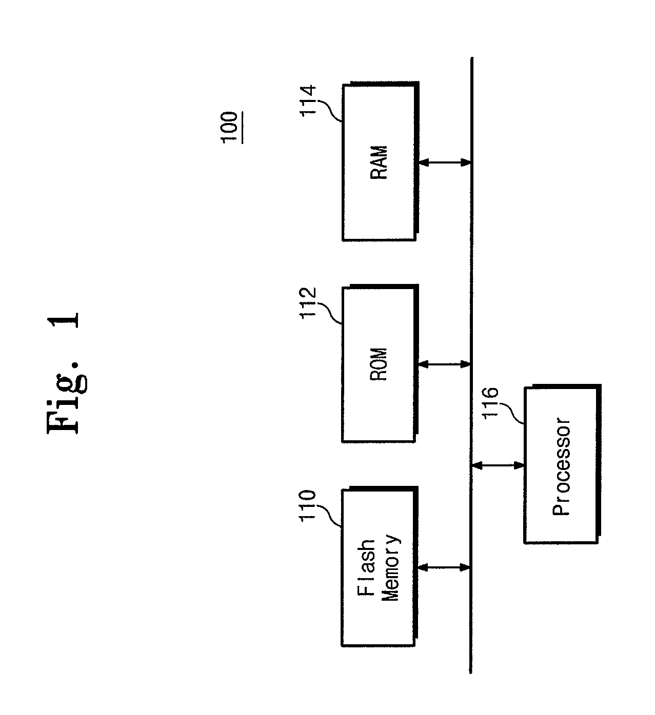
[0033]As shown in FIG. 1, a memory mapping system is indicated generally by the reference numeral 100. The system 100 includes a processor 116, a flash memory 110 in signal communication with the processor, a read-only memory (“ROM”) 112 in signal communication with the processor, and a random access memory (“RAM”) 114 in signal communication with the processor. The ROM 112, for example, may include program steps executable by the processor 116 for providing read and write commands to read data from and write data to the flash memory 110 or the RAM 114. The read and write operations responsive to the commands are performed in the flash memory 110 in accordance with memory mapping embodiments of the present disclosure In addition, the ROM 112 and the RAM 114 may store related data structures and / or application program steps executable by the processor 116.

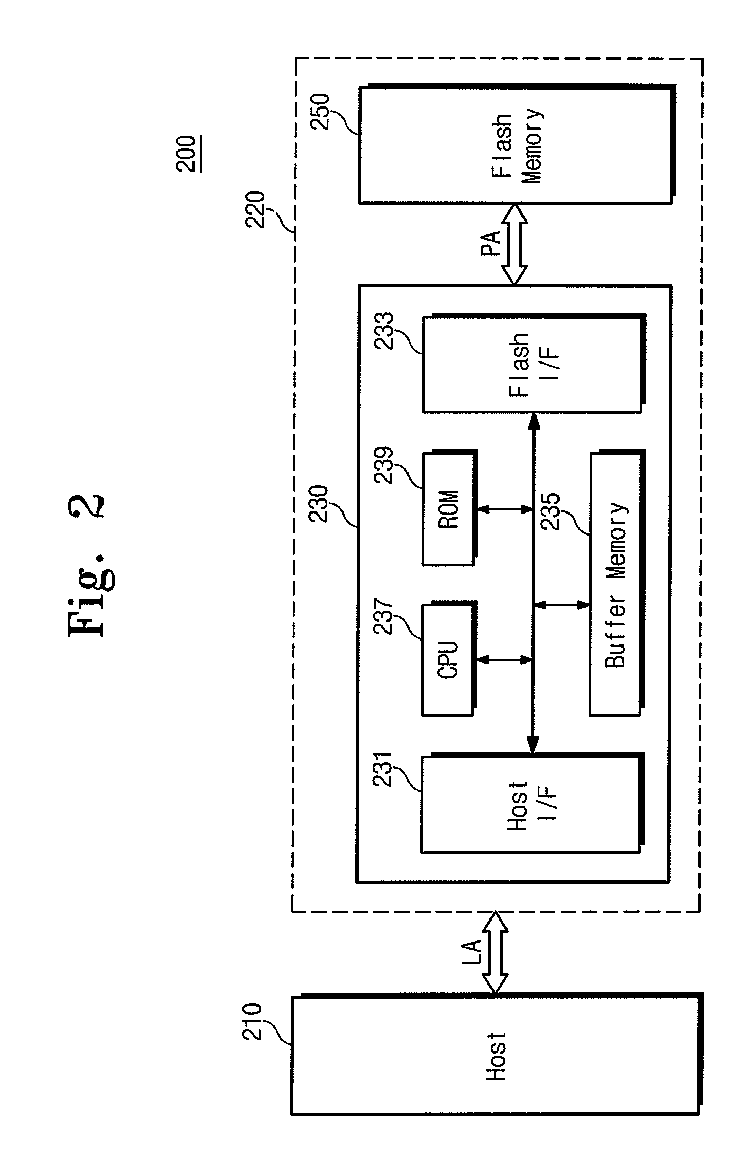
[0034]Turning to FIG. 2, a flash memory card system is indicated generally by the reference numeral 200. The system 200 may be a p...


PUM


Abstract

A system and method for memory mapping are provided, the system including a logical unit to physical unit map table, data unit groups in signal communication with the map table, and log unit groups, each associated with a corresponding one of the data unit groups, where updated data for any data unit within one of the data unit groups is stored in any log unit within the corresponding one of the log unit groups, and the method including receiving write data for a logical unit number from a host determining which of a plurality of data block groups comprises the logical unit number, and storing the write data in any unfilled log unit of a log block group corresponding to the determined data block group.

Description

CROSS-REFERENCE TO RELATED APPLICATION[0001]This application claims foreign priority under 35 U.S.C. §119 to Korean Patent Application No. P2007-0012198 (Atty. Dkt. ID-200610-028), filed on Feb. 6, 2007, in the Korean Intellectual Property Office, the disclosure of which is incorporated by reference herein in its entirety.BACKGROUND OF THE INVENTION[0002]The present disclosure generally relates to flash memory systems. More particularly, the present disclosure relates to flash memory systems with mapping tables.[0003]Emerging portable electronic devices, such as computers, digital cameras, digital music players, cellular telephones, personal data assistants, and the like, have made increasing use of flash memories, particularly flash cards. A flash card may be a SSD, SD card, MMC, Memory Stick, or an embedded card such as moviNAND, GBNAND, iNAND and the like.[0004]Hosts generally communicate with flash memories using a flash translation layer (“FTL”). The FTL may include firmware st...

Claims


Application Information

Patent Timeline
IPC IPC(8): G06F13/00
CPCG06F2212/7201G06F12/0246G06F12/06G06F12/00
Inventor CHEON, WON-MOONLEE, YANG-SUP
Owner SAMSUNG ELECTRONICS CO LTD
Why Eureka
Try Eureka