

Optical film and polarizing plate
a technology of optical film and polarizing plate, applied in the direction of polarizing elements, mountings, instruments, etc., can solve the problems of large display unevenness etc., to improve the display characteristics of liquid crystal display devices, reduce light leakage and color shift, and reduce display characteristic change
- Summary
- Abstract
- Description
- Claims
- Application Information
AI Technical Summary
Benefits of technology
Problems solved by technology
Method used
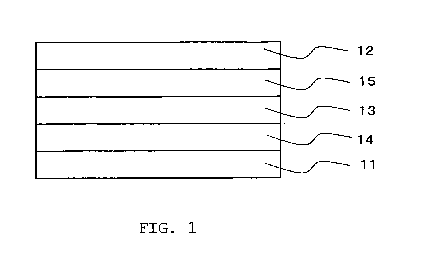
Image

Examples
example 1
Fabrication of Optically-Compensatory Films of the Invention (Films for First Optically-Compensatory Layer) 101 to 105, and 107 to 111
[0286]The ingredients were mixed in the ratio indicated in Table 1, thereby preparing cellulose acylate solutions. Using a band caster, the cellulose acylate solution was cast, the resulting web was peeled from the band, and then stretched under the condition shown in Table 1. After stretched, the film was dried, thereby producing cellulose acylate films 101 to 105 and 107 to 111 having the thickness shown in Table 1.
[Fabrication of Comparative Optically-Compensatory Film (Film for First Optically-Compensatory Layer for Comparison) 106]
[0287]A commercially-available norbornene polymer film, “ZEONOR” (by Nippon Zeon) was stretched under the condition shown in Table 1, thereby producing a norbornene film 106.
[0288]Thus fabricated, the films were analyzed for the three-dimensional birefringence thereof at a wavelength of 450 nm, 550 nm and 630 nm, using ...
example 2
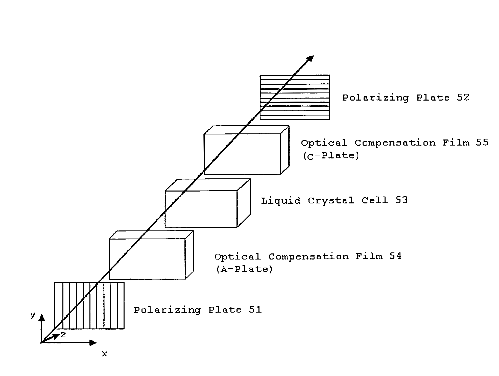
Construction of Liquid-Crystal Display Devices 51 to 67
[0334]In the same manner as in Example 1 but changing the polymer type, the amount of the retardation enhancer, the stretching temperature and the stretching draw ratio, various films for first optically-anisotropic layer and films for second optically-anisotropic layer were fabricated; and the films were stuck to a polarizing film to produce polarizers; and using them, VA-mode liquid-crystal display devices 51 to 67 were constructed in the same manner as above, as in Table 7 below.
[Organoleptic Evaluation of Liquid-Crystal Display Devices 51 to 67]
[0335]Thus constructed, the liquid-crystal display devices 51 to 67 were organoleptically tested and evaluated according to the following criteria.
[0336]The devices were organoleptically tested for light leakage and color shift in the oblique direction in the black state in a dark room.
(Evaluation Criteria for Light Leakage)
[0337]⊚: Little light leakage found in every polar angle dire...
example 3
Fabrication of Optical Film 501
(Preparation of Cellulose Acylate Solution 11)
[0350]The following composition was put into a mixing tank, and stirred to dissolve the ingredients, thereby preparing a cellulose acylate solution 11.
[0351]Composition of Cellulose Acylate Solution 11
Cellulose Acetate having a degree of acetyl substitution100.0 mas. pts.2.70 and a degree of polymerization 420Triphenyl Phosphate (plasticizer) 6.0 mas. pts.Biphenyl Phosphate (plasticizer) 3.0 mas. pts.Methylene Chloride (first solvent)402.0 mas. pts.Methanol (second solvent) 60.0 mas. pts.
(Preparation of Mat Agent Solution 12)
[0352]The following composition was put into a disperser, and stirred to dissolve the ingredients, thereby preparing a mat agent solution 12.
Composition of Mat Agent Solution 12
[0353]
Silica Particles having a mean particle size of 20 nm 2.0 mas. pts.(AEROSIL R972, by Nippon Aerosil)Methylene Chloride (first solvent)75.0 mas. pts.Methanol (second solvent)12.7 mas. pts.Cellulose Acylate S...
PUM
 Abstract
- wherein the in-plane retardation thereof at a wavelength of 550 nm, Re(550), satisfies Re(550)>20 nm and the Nz value thereof (Nz=Rth(550)/Re(550)+0.5) satisfies 1.1≦Nz≦5, is disclosed. And a polarizing plate comprising the optical film is also disclosed.
Description
Claims
Application Information