Optical lens module
a technology of optical lens and optical module, applied in the field of compact optical lens module, can solve the problems of requiring a relatively high manufacturing precision, a relatively complex manufacturing process, and a tendency to wear out of the screw thread teeth
- Summary
- Abstract
- Description
- Claims
- Application Information
AI Technical Summary
Benefits of technology
Problems solved by technology
Method used
Image
Examples
first embodiment
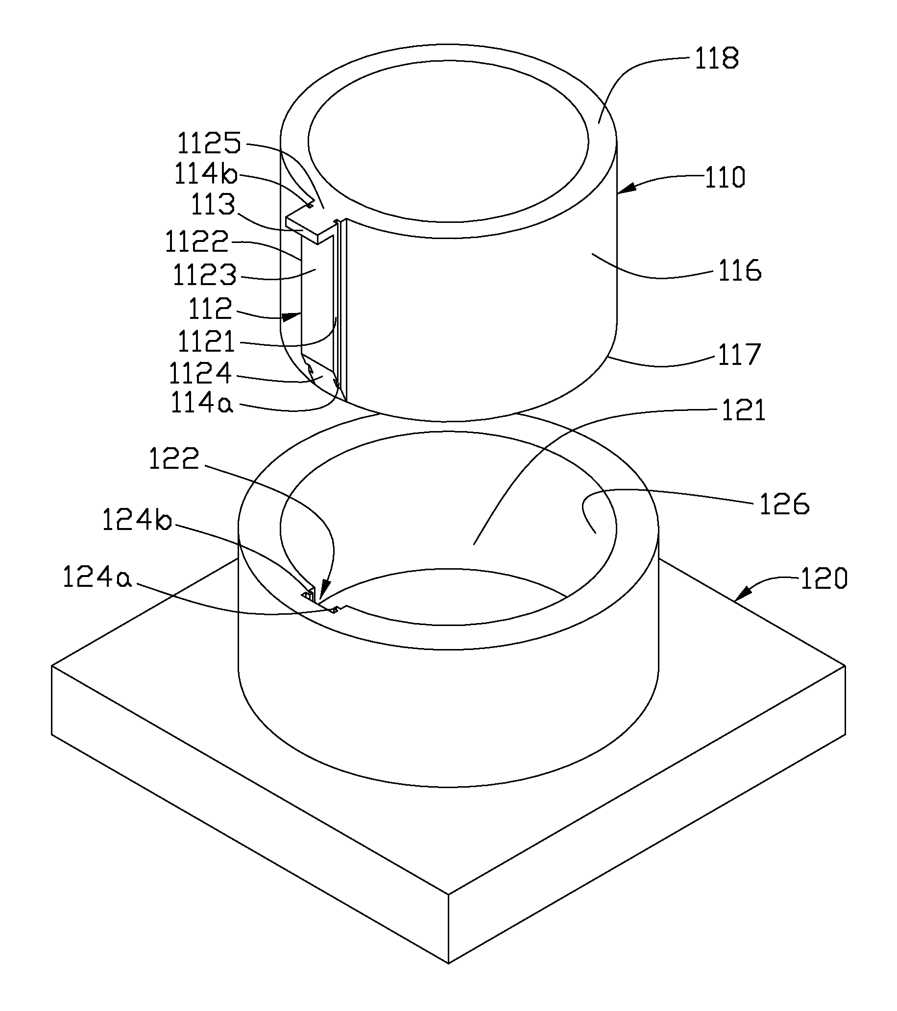
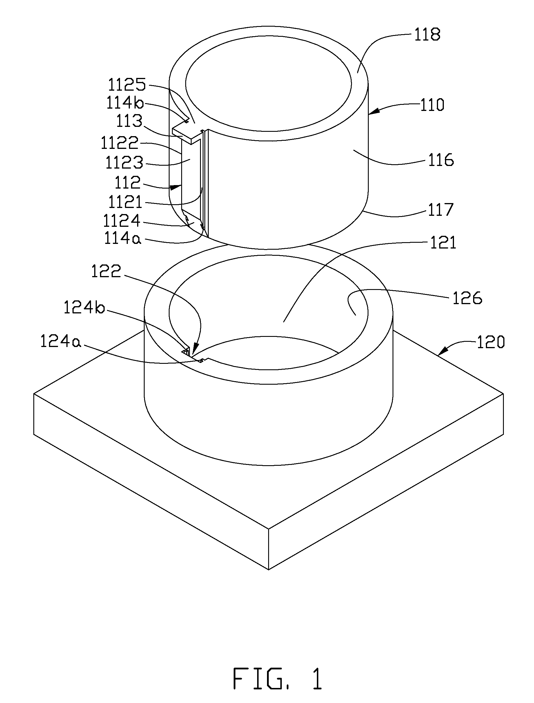
[0017]Referring to FIG. 1, an optical lens module 10, in accordance with a first embodiment is illustrated. The optical lens module 10 includes a lens barrel 110 and a barrel base 120. The barrel base 120 defines a receiving housing 121 configured for accepting the lens barrel110 therein. The receiving housing 121 extends essentially perpendicularly from the main portion (not labeled) of the barrel base 120. The optical lens module 10 may include other optical elements to realize their corresponding optical functions. The lens barrel 110 may, usefully, have a cylinder shape, e.g., a circular cylinder shape. The receiving housing 121 of the barrel base 120 has a cylinder shape corresponding to the lens barrel 110, e.g., a circular cylinder shape. The lens barrel 110 and the receiving housing 121 share a longitudinal axis that concurrent with the optical axis of the optical elements carried within the lens barrel 110.
[0018]The lens barrel 110 includes a first end surface 117, an oppos...
third embodiment
[0026]Referring to FIG. 3, an optical lens module 30, in accordance with a third embodiment, is shown. The optical lens module 30 includes a lens barrel 310 and a barrel base 320. The barrel base 320 includes a receiving housing 321 extending essentially orthogonally from the main portion 323 thereof. At least a positioning slot 312 is created in an external wall 316, along an axis (i.e., longitudinal / optical axis) of the lens barrel 310. At least a positioning block 322 corresponding to the positioning slot 312 is arranged on an internal wall 326 of the receiving housing 321. The positioning block 322 may, for example, be a prism, e.g., a hexagonal prism. Correspondingly, a cross section profile of the positioning slot 312 should match that of the positioning block 322, for example, a mating polygon, e.g., hexagon.
[0027]A protrusion portion 313 may extend transversely / radially from any position of a second end surface 318 of the lens barrel 310. In the present embodiment, the protr...
fourth embodiment
[0028]Referring to FIG. 4, an optical lens module 40, in accordance with a fourth embodiment, is shown. The optical lens module 40 includes a lens barrel 410 and a barrel base 420, with the barrel base 420 further defining a receiving housing 421. The lens barrel 410 includes a first positioning slot 412 and a second positioning block 415. The first positioning slot 412 and the second positioning block 415 are located on an external wall 416 of the lens barrel 410, along a longitudinal / optical axis direction of the lens barrel 410. The barrel 420 includes a first positioning block 422, corresponding to the first positioning slot 412, and a second positioning slot 425, corresponding to the second positioning block 415. The first positioning block 422 and the second positioning slot 425 are located on an internal wall 426 of the receiving housing 421. The first positioning slot 412 and the first positioning block 422, as well as the second positioning block 415 and the second position...
PUM
 Abstract
Description
Claims
Application Information
 - R&D
- Intellectual Property
- Life Sciences
- Materials
- Tech Scout
- Unparalleled Data Quality
- Higher Quality Content
- 60% Fewer Hallucinations
Browse by: Latest US Patents, China's latest patents, Technical Efficacy Thesaurus, Application Domain, Technology Topic, Popular Technical Reports.
© 2025 PatSnap. All rights reserved.Legal|Privacy policy|Modern Slavery Act Transparency Statement|Sitemap|About US| Contact US: help@patsnap.com


